Collaborative Design Part 3: Crossing the ECAD/MCAD Bridge

Table of Contents
Interfacing between electrical and mechanical design software is one of the most important forms of design collaboration in modern electronic design. As PCBs become smaller and more dense, and as mechanical housing restrictions become tougher, there is a great need for seamless design data transfer. For the third installment in this blog series, we'll take a look at some of the options available for crossing the boundary between electrical and mechanical domains.
So now that we’ve established the inner workings of a collaboration system (see Part 1 and Part 2 of this blog series), let’s check out one of the applications of collaborative design. As discussed in Part 1 of this series, the term design collaboration can mean different things to different people, and can span a single domain or several. Some of the different domains include electronic design (PCB/Schematic/), mechanical design, supply chain, manufacturing, and other spaces accessed during a product’s lifecycle.
ECAD/MCAD collaboration, between the electrical and mechanical design domains, is particularly important as PCBs become smaller and more densely populated, and as mechanical constraints become more strict in turn. Having a good bidirectional interface between the two domains can make life infinitely easier for all parties involved, and can help ensure a cleaner design cycle, with greater product integrity in the long run. While there are several options for interfacing across CAD software, there are currently two standards commonly used.

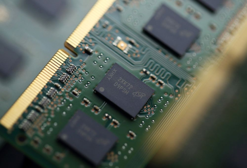
Figure 1: Having the ability to interface between electrical and mechanical CAD software is essential for modern electronic design.
STEP (Standard for The Exchange of Product model data)
A true 3D representation of design data, STEP models can be used for PCBs, components, mechanical assemblies/housings, and any other design files which may be collaborated on by multiple designers using different programs. It’s important, however, to understand both the benefits and limitations associated with using STEP for bidirectional transfer between programs.
|
Benefits |
Limitations |
|
Adheres to ISO 10303 standard, meaning all design models are consistent and follow the same protocol. |
Since it is intended as a common format for data exchange between programs, some features exclusive to each piece of software will inherently be lost. |
|
Having such a common and generic format means several component manufacturers make 3D models of their available for download. |
Does not lend itself well to complex design features, and the addition of some items (such as copper traces, silkscreen, etc.) can increase file sizes significantly. |
|
Being a true 3D format (instead of a pseudo 3D / “2.5D” format) allows for complex model features and curvature, such as folded board shapes for Rigid-Flex PCBs. |
Has no function for true collaboration, and simply requires manual checking by each to ensure design data is correct and up to date. |
The two Application Protocols (APs) under ISO 10303 used for 3D CAD data are AP203 (older format) and AP214 (newer format). More information about these APs can be found here.
IDF (Intermediate Data Format)
For several years, IDF was considered the de-facto standard file format for transferring design data between electrical and mechanical CAD software. In reality, IDF is not truly 3D, and is instead represented as so-called “2.5D”, that is, viewable as 2D in ECAD, and extrapolated using model height information to 3D in MCAD. Of course, this scheme does not lend itself to complex 3D shapes, which may be required for certain data exported to the mechanical domain, such as folded Rigid-Flex board shapes.
IDF is good for preliminary mechanical clearance checking, since component and board heights are recorded and transferred with the file, but there are limitations. If clearance checking or modelling is more involved, component bodies must be replaced post-transfer, meaning additional work for the mechanical, as well as potential issues matching body alignment and rotation.
Other Solutions for Electrical/Mechanical Interfacing
Native 3D™ PCB Editing
Including tools within ECAD software for mechanical design, or at least alignment, placement, and export of 3D mechanical models, allows much of the work to be done in a single software package. Altium Designer® includes capabilities for aligning 3D component models to footprints, modelling and clearance checking for housings/enclosures, and if necessary, standard exports of complex PCB features for MCAD interfacing.
ECAD/MCAD Collaboration Tools and Formats
Certain third-party tools enable better collaboration than could be offered using either of the aforementioned file formats. Using a more robust design data transfer system, these tools allow much more comprehensive bidirectional design, visibility and conflict resolution, as well as more complete integration with each software interface. Similarly, IDX (Incremental Data eXchange) offers this same sort of bi-directional capability in a vendor-neutral file format.
Where Does ECAD/MCAD Collaboration Go from Here?
With the inclusion of 3D editing features in most ECAD software packages, the need for good software file transfer solutions is dwindling, beyond perhaps the initial creation and import of mechanical data.
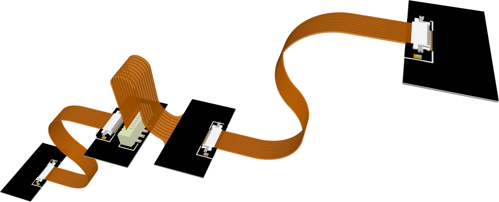
Figure 2: Complex electro-mechanical assemblies, such as multi-board designs connected through flex cabling, will be a driving force for ECAD/MCAD collaboration moving forward.
This doesn’t mean there is no need to support and improve such an interface, however. It simply means that true collaboration between software domains will become that much more important to the design process. More sophisticated projects, such as mutli-board designs and complex electro-mechanical assemblies, are still generally beyond the scope of a single domain. But that won't be for long. Our flagship PCB design software is changing ECAD/MCAD collaboration for the better.
Related Resources


Related Technical Documentation


Take advantage of the world's
most trusted PCB design system.
One interface. One data
model. Endless possibilities.
Effortlessly collaborate with
mechanical designers.
The world's most trusted
PCB design platform
Best in class interactive
routing
View License Options
Thank you, you are now subscribed to updates.