Perfect Styling for Your Organization with Altium 365: How to Keep Schematics Organized

We all had a moment when piles of annotated schematics were growing on our desk, and we started losing track of what was what. What revision is this? Did my colleague check it? Is this IC the new one, or the one that used to go up in flames every full moon?
In this article, I want to show you how to how to keep schematics organized and make a stunning personalized schematic template for your business that is ready for Altium 365 and the 21st century. We’re going to integrate the template with all fields and features needed to keep track of our projects in the cloud. You can then deploy it across your organization using Concord Pro on Altium 365.
Over the years I took inspiration from software development, governmental accessibility guidelines, and architectural drawings while learning how to keep schematics organized. Here is a series of tips and tricks to craft easily readable schematics and title blocks, which I hope will help you on your journey through the flood-lands of paper piles on your desk.
How to Keep Schematics Organized with the Perfect Template
Many aspects must be considered in crafting the perfect template, and I want to be honest with you, not every approach is going to work equally well. The right template should be readable by a broad age group and render well on your computer screen, paper, and old LCD monitors. More importantly, care must be taken, so the template displays all information needed to pinpoint your design both outside and inside your organization.
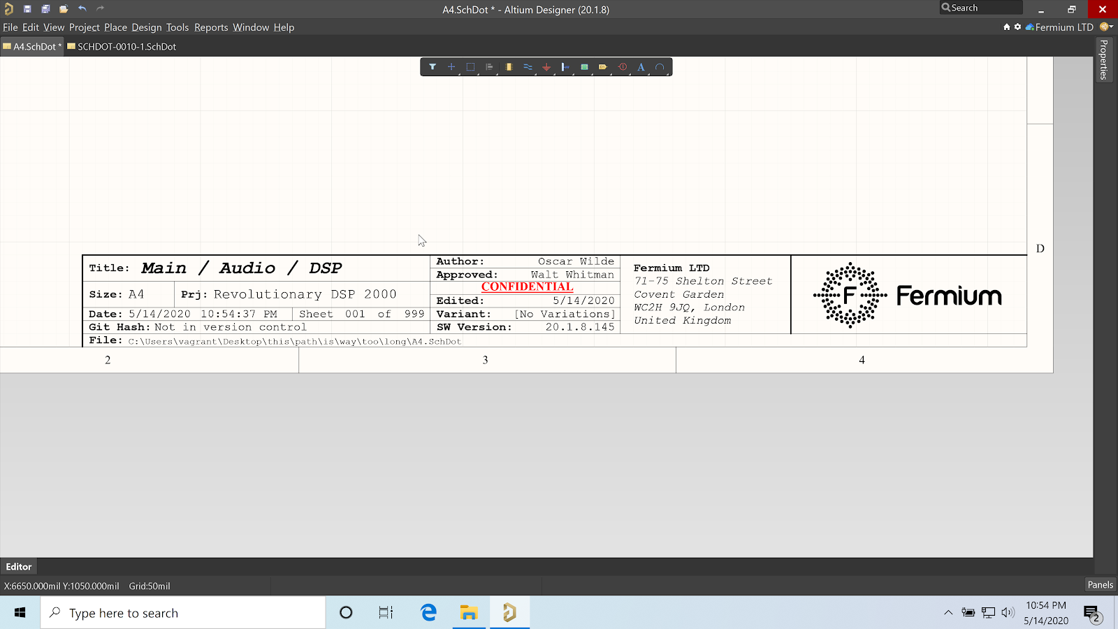
We should ask ourselves the following question: If our schematics were to be lost in the most unlikely of circumstances, is there enough information for it to be returned? If it were found again after two years, would we be able to pinpoint precisely where and when in the development process it originated? Creating hierarchical schematics is the first step in understanding how to keep schematics organized, but each schematic sheet needs to contain very specific information to aid organization. This information gets put into the title block and revision block to help everyone on your team stay organized.
Hierarchical Naming Convention
Altium Designer is probably the software with the most extensive support for hierarchical projects, and while you can sometimes get lost in the schematics if you implement the structure in a rush, it is a feature which allows you to keep big projects well-organized.
A hierarchical structure is one in which schematic sheets are placed one within the other through the use of sheet objects. This creates a parent-child relationship between different schematic sheets. Altium Designer does not (by default) display this structure on the schematic sheets, and while it’s easy to descend into sub-circuits by reading the schematic filename from the Device Sheet, it can be a little confusing to crawl back up from the sub-circuit to high-level schematics.
One tip I can wholeheartedly recommend for how to keep schematics organized is to enforce a similar naming structure in the directories that hold your design documents. For example, if we have a schematic for a digital audio equalizer, we may want to divide it into sub-circuits as follows:
- MAIN: High-level system view
- MAIN / POWER: power supply
- MAIN / AUDIO: high-level audio processing view
- MAIN / AUDIO / ADC: Analog to Digital converter stage
- MAIN / AUDIO / DSP: Digital Sound Processor stage
- MAIN / AUDIO / DAC: Digital to Analog Processor stage
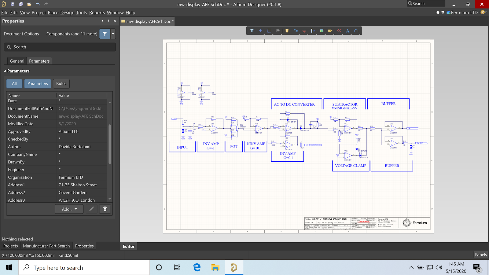
The hierarchical name constitutes our “Title” parameter, separated from “DocumentName”, which is generated automatically by Altium and resembles something like “audio_dac.SchDoc”.

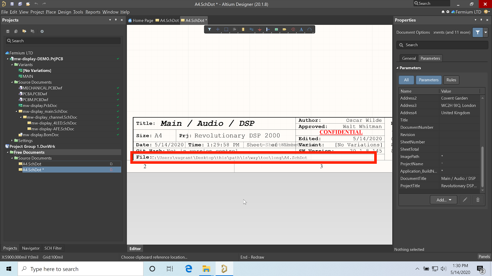
Support Very Long File Paths
Windows paths like “/Users/oscar.wilde/Documents/Project/AudioAmplifier2000/main_board.SchDoc” can reach up to 260 characters in length. It’s important to plan and allow enough space. Supporting the entire path instead of just the filename allows you to reduce error and can help you to pinpoint the computer that created the schematic file print through the username.
If you want to automatically add the path name for your schematic sheet to a title block, you need to include a path parameter when creating your schematic template. The path parameter is “DocumentFullPathAndName”. As shown below, this automatically places the path to the schematic file (both for the template and the finished schematic sheet) in the title block.
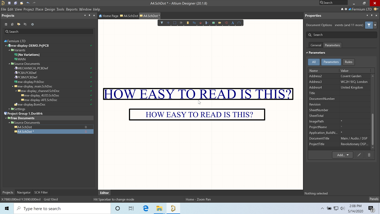
Use a Monospaced Font
Using a mono font may look a little bit weird—almost retro. Mono fonts resemble a typewriter, as the same amount of space separates each character. This is different from most variable-width fonts, where an “I” uses less space than a “K”.
Using a monospaced font allows you to compare paths and Git MD5 hashes on printed paper more quickly and makes the text size more predictable. In our example template, we’ll use Courier New as it looks good and is available by default on Windows computers. More modern monospace Sans-serif fonts like Source Code Pro can be downloaded and installed, but I would not recommend it unless you have a system in place to deploy them automatically on all computers.

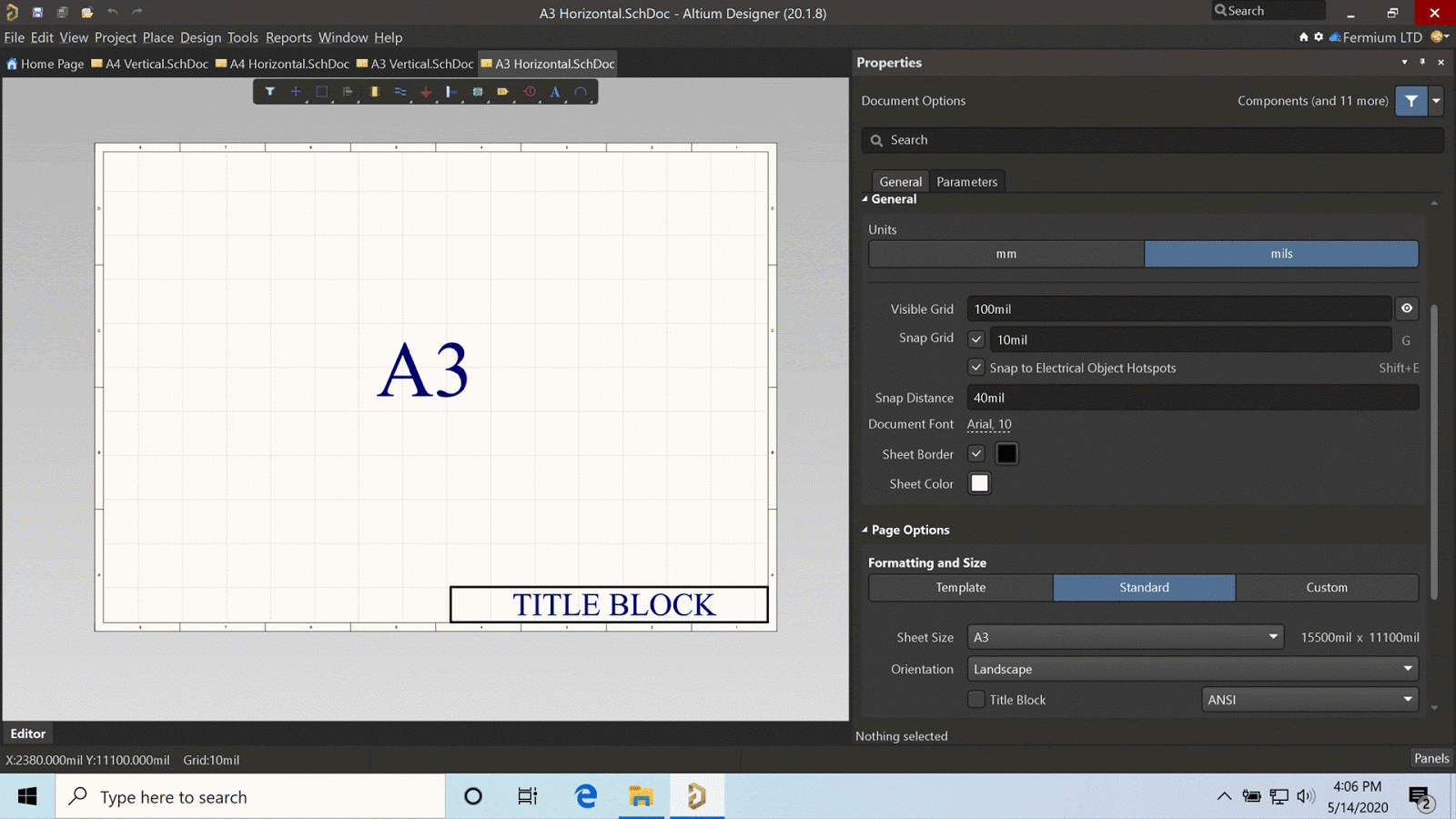
Choose the Right Size for the Title Block
In Europe, the two most popular paper sizes are A4 and A3, roughly equivalent to A and B paper sizes used in the United States. Many templates for technical drawings that can be found online, especially those based on earlier Altium Designer templates, have title blocks of about 1/3 the page width.
I have found it’s neither practical nor elegant to attempt cramming too much into a title block. As any typographer can attest, fonts require whitespace around them to be legible.
I recommend using the shorter side of an A4 (A type in the US) sheet as a reference. It enables to create schematics in both portrait and landscape and looks clean and proportional in all most common paper sizes
Always Include the Engineer Name and the Company Address
I have seen many commercial enterprise projects in which some critical information was missing from the title blocks. The most common one is the name of the engineer responsible for the drawing. Some companies decide to omit the names out of secrecy, but I think it’s fundamental to keep track of the individual responsible for a circuit, as well as to provide proof of merit for the designer.
Writing out the designer name can also help to avoid unnecessary “finger-pointing”: if there is an issue with the design, it’s the responsibility of the person indicated by the designer name to fix it. This simple tip can help many team managers keep their sanity.

Another piece of missing critical information is the complete name and address of your company. Many companies only write their name and logo, but think about this: How many companies with the same name as yours exist?
Mine is called Fermium, and just in the UK, several limited companies with the same or similar name have been registered in recent years. Similarly, there are many companies called Altium, some of which could be Altium subsidiaries or associates, but undoubtedly not all of them.
Office addresses tend to change less frequently than website domains and telephone numbers, and leave a more extensive paper trail. Who is to say your design won’t have a comeback in 10 years after you’ve changed jobs and the company has been acquired a couple of times? Similarly, I recommend adding a company logo to make your design easily identifiable. If you are a freelancer, crafting a logo communicates professionality and reliability.
Altium Designer has schematic template several parameters for adding the address and engineer name, such as:
- Address1 through Address4 for a standard international multiline address
- ApprovedBy
- Author
- CheckedBy
- CompanyName
- DrawnBy
- Engineer
- Organization
You can choose which one to use depending on your organization's plane for how to keep schematics organized. More information can be found in the Altium Designer documentation.
Track the Variants
Murphy’s law: Every potentiometer will rotate in the wrong direction. I fall prey to her more times than not, and for this reason, I always add four 0-ohm resistors around any potentiometers to switch the direction at the assembly stage.
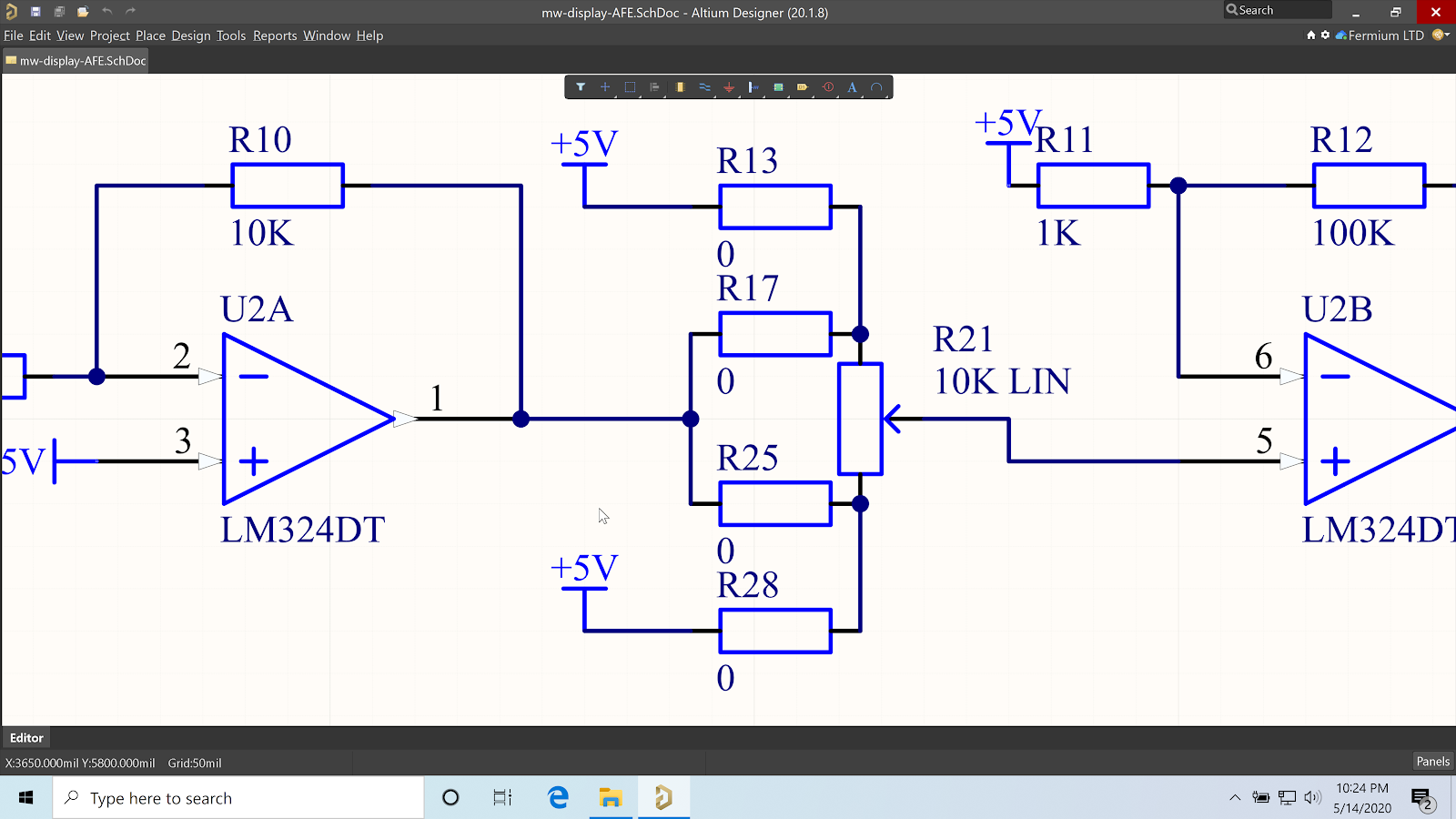
Similarly, I’m often not sure if my circuit will work with the internal 100/200 kOhm pull-ups in the microcontroller, or if it’s going to require an external 10/47 kOhm resistor, thus I always leave an unpopulated resistor. In a past company I worked for, we used to keep track of these “hypothetical” components by having resistors with part numbers such as “RES_DO_NOT_PLACE”, which were a source of confusion and frustration for our EMS suppliers.
A much cleaner way is to use variants: place all the components you need to place, then create a variant called “MAIN” with the default configuration. Update the OutJob, so only that variant is exported. You will be able to keep track of the unpopulated components in your schematic and Draftsman document with maximum clarity and minimal errors. The variant can be displayed in the title block through the parameter “VariantName”.
Another option is to simply mark specific components as DNP in your variant. Creating a variant and setting components as DNP eliminates the need to manually track which components will be DNP in your assembled board. If you're only going to be setting specific 0 Ohm resistors as DNP, a better option is to use solderable jumpers as you won't need to purchase and place additional components.
Keep the Text Legible at the Proper Page Size
Academic research in the topic of user interface design has long concluded that it’s good practice to keep the font size around 10 or 12 points, where 12 is readable by most age groups. The bare minimum page size is around 6 points. In our template, we’ll choose only font sizes in that range. By adopting a font size of 12, our A3 schematics are still readable when printed half-size to A4.
Add “Confidential” on Every Page
Most NDAs (Non-Disclosure Agreements) restrict the concept of confidential information to documents explicitly marked as such. Your schematics probably contain some of the most important trade secrets of your business. You should mark them with a big juicy “Confidential” stamp.

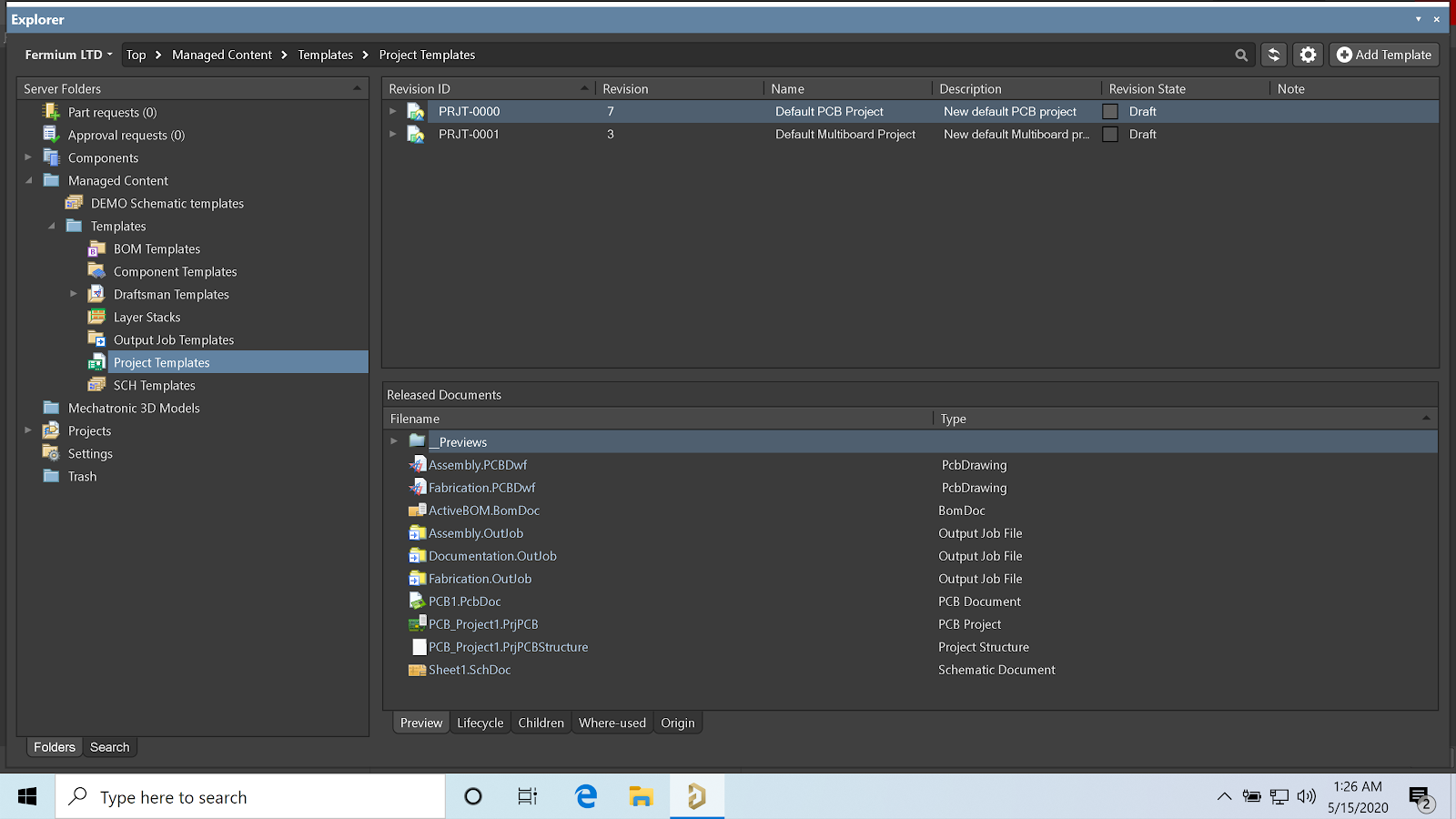
Create and Distribute a Schematic Template with Altium 365
If you want to help your entire team learn how to keep schematics organized, it starts with giving everyone access to the same schematic template. I have gone ahead and created a title block that matched all the criteria as mentioned earlier.
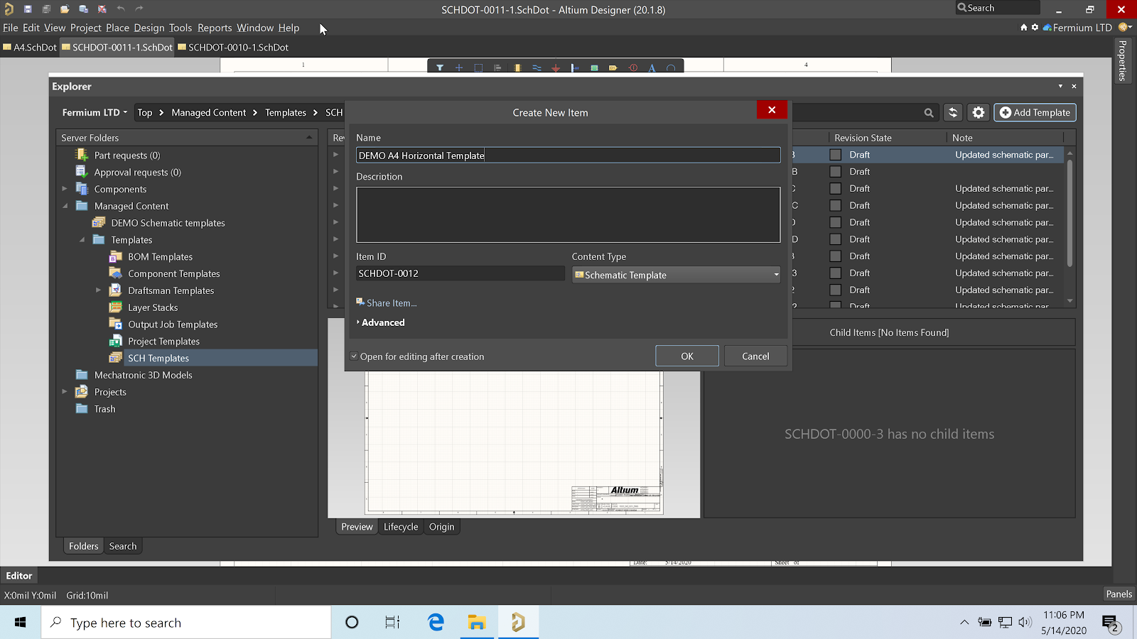
We can then create a new Schematic template inside of the Explorer panel, which will make it accessible to everyone involved in the organization. Other team members can use the template for new schematics, open it for editing, and copy-paste the title block into it.
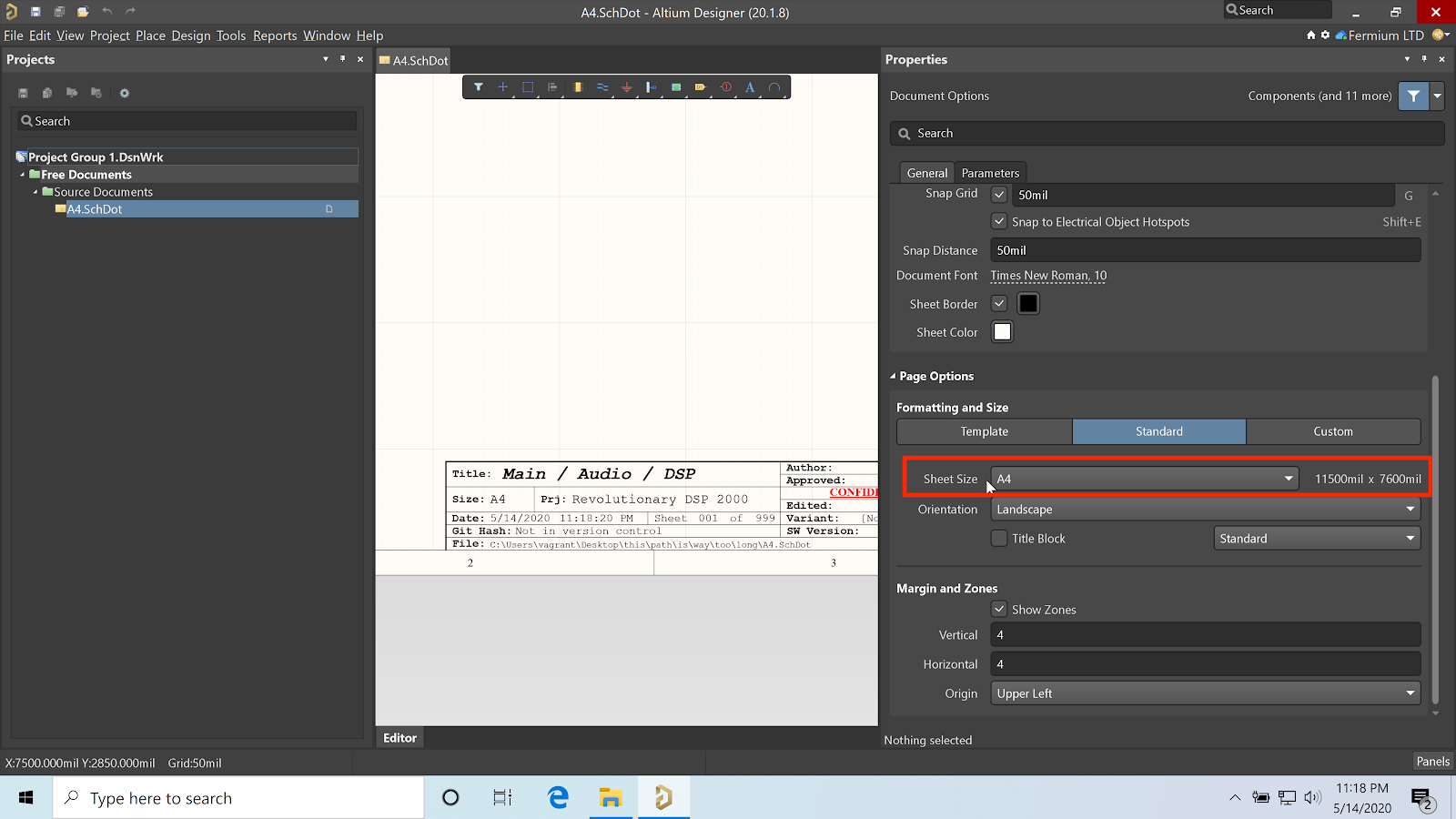
The size of the schematic page can be changed in the properties panel when no component or schematic object is selected.
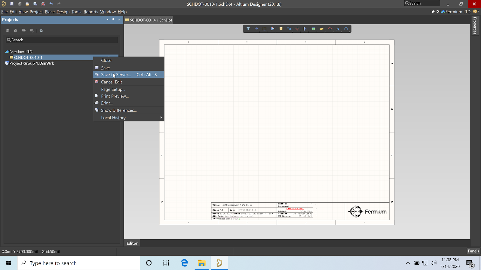
Once completed, the Schematic template can be uploaded to Concord Pro on Altium 365 by using “Save to server” or the CTRL+ALT+S shortcut.
Create and Distribute a Unified Color Palette
I’m going to sound like an interior designer for a while—maybe it’s my Italian blood. Choose your colors wisely.
If you’re lucky enough to still wander in the first middle-half of your life, you may be tempted to use a reduced-contrast palette in your drawings, such as blue and light blue. Resist the urge: your older colleagues may already have a decreased contrast sensitivity. Your schematics should not encode information in color, and should be printable in monochrome.
I have personally switched away from the blue/yellow/red/green/black palette of Altium Designer to an almost blue-only or a black-only, where only NetTies and Text Strings having different colours. If you want to choose more than one colour, I recommend choosing red and blue.
The human eye, for the majority of people, has three different colour-sensitive cones. The following chart depicting shows the sensitivity of cones in the human eye over the visible spectrum. Green and red overlap a lot, which partially explains why red-green is the most common form of colour-blindess.

Red and blue, on the other hand, are far apart on the spectrum, and are thus considered easily distinguishable by most colourblind folks. Some EDA suites lock their styling to aid sales, as it helps to create a coherent brand, but Altium Designer does not impose this type limit. In the example below, I’ve created an all-blue style by changing the default schematic objects in the preferences.

I’ve then created a preference folder in Concord Pro and used “Send to Server” under “Save” in the preferences dialog. Other workspace users can access this colour scheme and reuse it in new schematics and projects.

When the preferences are released to the server, you can choose to apply them automatically to every engineer workstation and lock them, apply them when Altium Designer is first installed, or do not apply them at all, leaving every engineer free to pull them as they please.
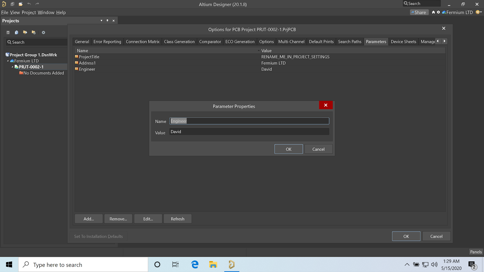
Distributing a Pre-configured Project Template
Keeping team members is sync goes beyond understanding how to keep a schematic organized with templates. Luckily, just as Altium Designer allows us to use templating for Schematic or PCBs, we can do the same for the project file. Project templates can also be used to enforce organization across a PCB design team. Some of the custom parameters we have adopted in the schematic template—for example, ProjectTitle—should be added at the project-level in every PrjPcb, so they are easier to remember and edit.
We should start by creating a new project template from the Explorer panel taking care of selecting “Open for editing after creation”.
We can then edit the parameters in the project settings and add our own.
The project can be edited and sent to the server by using “Save to Server” or the CTRL+ALT+S shortcut.

Conclusions
Through Altium Designer’s advanced template capabilities and Concord Pro on Altium 365, we can create and distribute schematic templates, project templates, and settings to our entire organization. Adopting a template that references all required information can ease our job as engineers, and shine a bright light on us as freelancers when showing schematics to customers. This gives design team a head start on understanding how to keep schematics organized.
Choosing a different color palette for our schematic objects can make them more intelligible to older and colorblind colleagues.
You can download a copy of the template we have just created in this GitHub repository: Fermium/AltiumTemplates.
Whatever template design or colors you choose to make your design shine, Altium 365 and Altium Concord Pro can help you distribute and manage coherent templates, components, projects, and settings for every engineer on your team.

About Author
Related Resources


Related Technical Documentation
Table of Contents
Take advantage of the world's
most trusted PCB design system.
One interface. One data
model. Endless possibilities.
Effortlessly collaborate with
mechanical designers.
The world's most trusted
PCB design platform
Best in class interactive
routing
View License Options
Thank you, you are now subscribed to updates.