Thunderbolt Design: Adaptable High Speed Serial Data in Your PCB

High resolution displays, external GPUs, super-fast external storage, 10G Ethernet adapters... the list of applications for Thunderbolt 3 and 4 designs goes on. The Thunderbolt protocol was originally developed by Intel in collaboration with Apple and released in February 2011, and the protocol has evolved to be compatible with USB-C. Today, Although originally a proprietary protocol which required a license and royalty to use in new products, Intel announced that the Thunderbolt 3 and later protocols would be royalty-free to OEMs and IC manufacturers with the goal of boosting adoption of the protocol.
Thunderbolt 3 devices provide bidirectional data transfer rates reaching up to 40 Gbps, a massive improvement over USB 3.1 Gen 2 data transfer at 10 Gbps. The next generation of Thunderbolt 4 devices is starting to hit the shelves, and product designers can add high speed communication with major computer peripherals using the Thunderbird 3 or 4 protocols. Although Thunderbolt products use a USB-C connector, the design constraints on Thunderbolt design are more stringent due to the higher data rate. In addition, there is the matter of choosing a device topology to extend data and power out to peripherals. If you’re planning to add Thunderbolt to your next design, take a look at our overview of Thunderbolt design to help you get started.
Basics of Thunderbolt Design
The Thunderbolt protocol combines PCIe and DisplayPort into two serial signals and provides these protocols over a USB-C connection. DC power is provided over a USB-C cable, and the protocol supports up to six peripherals per connector. The PCIe portion of the interface can also can also be as a virtual 10G Ethernet interface; the user simply needs an adapter to provide an Ethernet connection. Access to these protocols over a single interface makes Thunderbolt a much more flexible protocol than USB-C.
Thunderbolt 3 vs. 4
Now that Thunderbolt 4 is available and Intel’s newest Tiger Lake processors will support this more advanced protocol, it’s worth comparing the two protocols. The table below summarizes some of the important specifications in Thunderbolt 3 and 4.
|
|
|
|
|
|
|
|
|
|
|
|
|
|
|
|
|
|
|
|
A key difference between Thunderbolt 3 and 4 is that Thunderbolt 4 is compatible with the USB 4 protocol; in fact, USB 4 was designed based on the Thunderbolt 3 standards. However, USB 4 is still limited to its maximum data rate as defined in the standard. Depending on how the USB standards evolve going into the future, it’s also possible that Thunderbolt will evolve to continue supporting faster USB data rates.
What Goes Into Thunderbolt 3 and 4 Layout?
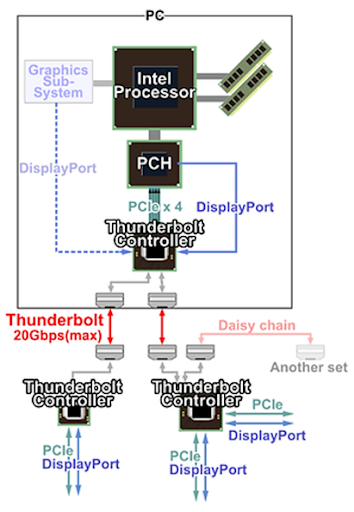
Combining these digital protocols into a single interface requires using some specialty components to control data transfer between a host and downstream peripherals. In addition, there is the need for these devices to run on Intel’s chipsets in the PC or server, while the external devices require Thunderbolt controllers to receive data and transfer it to other devices. The block diagram below shows Intel’s system view, where an Intel chipset interfaces with a Thunderbolt controller in the host. Data is then transferred over USB-C to the Thunderbolt controller in the peripheral device. Finally, the device controller provides digital data to a peripheral over the PCIe or DisplayPort protocols.
In terms of layout and routing, Thunderbolt designers need to follow many of the same rules used in PCIe, Thunderbolt, USB, Ethernet, and other high speed serial protocols with ~Gb data rates. Thunderbolt is often used with docking stations that include multiple high speed interfaces (e.g., all of the above plus HDMI, audio, VGA, etc.), so suppressing interference and differential crosstalk is a prime concern.
Here are some of the important component selection guidelines and layout guidelines to follow in these systems.
- Follow best practices and design guidelines for PCIe layout and routing, which requires controlled impedance and length tuning for PCIe lanes.
- Select the right power management components to support USB-PD in your device. Designs will need to provide up to 100 W (20 V/5 A maximum) under the USB-PD standards.
- Try to prevent PCIe and DisplayPort lanes from crossing near other digital interfaces after breaking these out from the host controller.
- Take advantage of ground planes and internal layers to provide isolation between digital protocols in different board sections.
- Follow length matching guidelines on differential pairs in the design to ensure maximum common-mode noise suppression.
- Follow best power integrity practices with adjacent power/ground planes to ensure stable power delivery in these high speed digital protocols.
When you need to layout PCIe, DisplayPort, or any other high speed protocol, you need to use the industry’s best set of PCB layout and routing tools. The rules-driven design engine in Altium Designer® includes an integrated electromagnetic field solver from Simberian to help you design impedance controlled channels and follow important rules for Thunderbolt design. You can also use the integrated pre-layout and post-layout simulation tools to simulate signal behavior in different portions of your system.
When you’ve finished your design, and you want to share your project, the Altium 365™ platform makes it easy to collaborate with other designers. We have only scratched the surface of what is possible to do with Altium Designer on Altium 365. You can check the product page for a more in-depth feature description or one of the On-Demand Webinars.


About Author
Related Resources


Table of Contents
Take advantage of the world's
most trusted PCB design system.
One interface. One data
model. Endless possibilities.
Effortlessly collaborate with
mechanical designers.
The world's most trusted
PCB design platform
Best in class interactive
routing
View License Options
Thank you, you are now subscribed to updates.