Concord Pro and Component Creation
Table of Contents

Altium Concord Pro™ as a standalone product and brand name has been discontinued and the capabilities are now available as part of our Altium enterprise solutions. Learn more here.
Introduction
First off, before I say anything, the more that I have been using Altium Concord Pro™, the more I like it. In fact, I love it. Altium has surprised me many times with the quality of the tools they put out. A few examples: Draftsman®, ACTIVEBOM® or ActiveRoute®, and Concord Pro (which I would categorize as one of the best). How have I survived up to this point without them?
I know through my involvement with Altium and the fact that I use the tool just about every day, that the philosophy that drives them is to place into the hands of designers, what they need to make their jobs easier. Concord Pro delivers.
I recently saw an advertisement for the New 2020 Corvette. It is an absolute Beast. 6.2-liter V-8 500 horsepower 470 foot-pounds of torque at 5,150 rpm. What was very surprising was that it goes from 0-60 MPH (100 Km) in all of THREE SECONDS. I wonder if you need extra medical insurance for the whiplash that you would get just taking off like that. That’s done by using gears 1-5 of the total 8-gears available, but, I thought what happens if the driver is in the habit of never shifting out of 1st gear? What an absolute waste that would be; all that power left unused.
The same way you would never miss out on this beast’s power, you shouldn’t miss out on your ECAD software power!
Why we do the same thing with our ECAD software (whatever it is we’re using)? With Altium, and now with Concord Pro, we have one of the most powerful tools on the market. However, many PCB Designers never get it out of first gear. That is not a condemnation, but rather a challenge for you, the designer. It’s time to shift gears. Concord Pro is our 2020 Corvette—are you ready to go from 0-60 in three seconds?
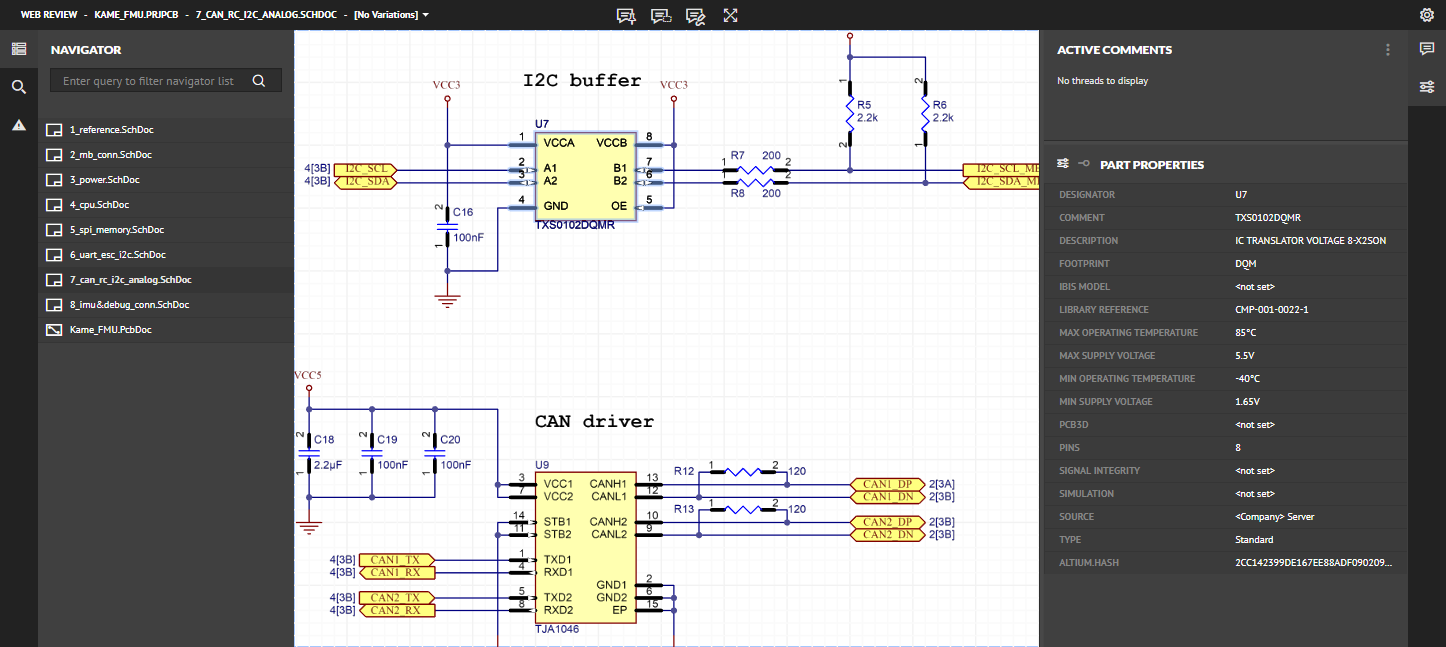
Concord Pro shifting the gears on Component Creation.
The very first thing I noticed when I started to use Concord Pro was how simple it was to create components. There was a time that all the individual parts of the Schematic symbol, the Footprint, 3D Model, the parametric information, sourcing, all had to create it from scratch. The only vital keystrokes needed were CTRL+C and CTRL+V for the copy and pasting the needed information.
What now happens is that it connects with the Octopart database, where all the information and models are already attached to the component. All that information is automatically brought in within seconds. My first response when I saw that was WOW.
But with that level of efficiency and power driving the process, it means introducing changes to how we would do things.
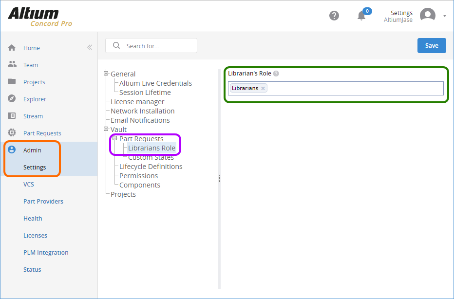
Component Creation Pre-Requisites
It is vital to make sure that a few Pre-Requisites are in place before creating any components.
First, an exhaustive search is done of the library to assure that the component does not already exist.
Those who know me, know my disdain for multiple libraries. However, the same risk is there when you have multiple duplicate components. With such an automated process, it is easy to rush things and skip this critical step.
The second pre-requisite is having the part number you wish to create and the component category and family. These tell us what you are creating and where it is to be stored.
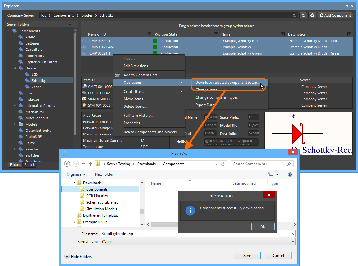
Lastly, just a check of the Altium Vault®, for those who are not familiar with this phenomenal resource, Altium has created their own resource library. Which I must say is an underutilized tool. It only makes sense that if the component already exists there, then use it directly to your design or download it and put into your local Altium Concord Pro library.
Automatic Component Creation
By selecting a category and family, then hitting <Add a Component>, the new Component Creation window opens. Enter the part number you want to create in the name field. The search begins, and your selection is on a list.
For example, we want to create the TCA9509DGKR, which is an IC ReDriver I2C 1CH using the package of an 8VSSOP. Enter the part number under name. (Warning get ready to shift gears and take off.) Automatically, all the information is loaded into your component. I do keep reminding Altium that some of us still work by the hour and with this much power at our fingertips, we need to come up with new excuses for why things took so long.
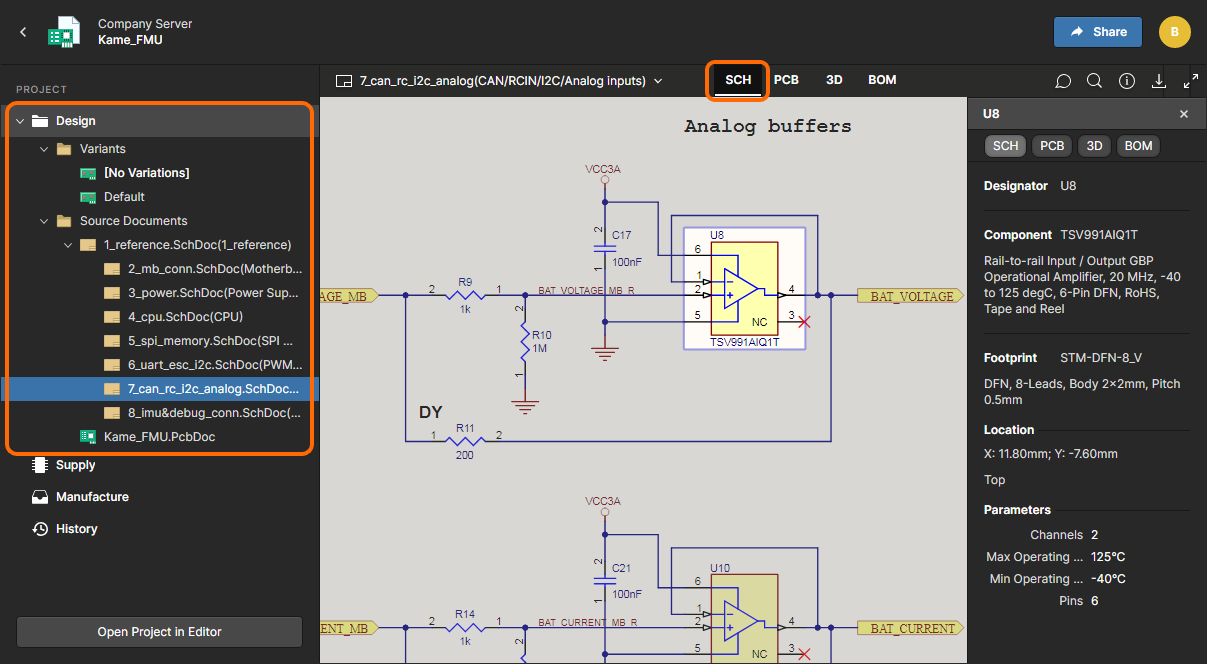
Concort Pro interface for component creation is straightforward. You can enter the component name here, and concord pro will automatically pull the rest.
With this much efficiency, there is a significant check to conduct. Concord pulls the models that are available, which means that you may already have them. In this particular example it uses the 8VSSOP footprint and 3D model, and well after a search in our models we find that we already have those in our library. It is effortless to replace any information or models if we need to.
Concord Pro is not just intuitive, but also full of features
Manual Method
Every time you create a component using the automatic method, there is some chance that the model is unavailable. With this they must be created manually by doing it “by hand”, or follow my recommendation, which is to use the available Schematic Symbol and Footprint Wizard. Still, even doing the Manual method of creating a component it is still much faster than how it used to be.
This does bring up a problem, though when dealing with various sources of components as someone who works with international vendors and components. Which is a stable and cheap source of components but when creating them they have no information (Asian Vendors not in Octopart®) which means they must manually be created. It is always best to have both a domestic and international source for the components to allow natural cross-referencing.
Labels for the image above.
Conclusion
Synergy. It is one of those business catchwords that is commonly dropped in meetings, usually to impress a boss. The technical definition is the interaction or cooperation of two or more organizations, substances, or other agents to produce a combined effect more significant than the sum of their separate effects. That is an excellent description a Component library. It has synergy. These individual and independent components are combined to create some of the most innovative things in the world. Because of that, it is easy to see the importance of your library and the importance of your librarian.
Would you like to find out more about how Altium can help you with your next PCB design? Talk to an expert at Altium and learn more about making design decisions with ease and confidence.
About Author
Related Resources


Related Technical Documentation

Take advantage of the world's
most trusted PCB design system.
One interface. One data
model. Endless possibilities.
Effortlessly collaborate with
mechanical designers.
The world's most trusted
PCB design platform
Best in class interactive
routing
View License Options
Thank you, you are now subscribed to updates.