Copper Wrap Plating in Your PCB
Table of Contents

No one wants to purchase a new electronic device, only to have it fail a week later. I’ve had the same flat screen monitor for over five years, and it is probably the toughest electronic device I’ve ever owned. If you love reliable designs, then you probably pay attention to industry standards designed to improve device lifetime.
Via plating in a PCB should be reliable enough that it can withstand shock and thermal cycling. This is where plating processes become critical, and the new IPC 6012E plating requirements specify plating techniques that are designed to improve the reliability of via-in-pad structures.
Copper Wrap Plating Structures
Filled via-in-pad structures require via holes be copper plated in order to route signals between layers in a multilayer PCB. This plating connects to other pads in via-in-pad structures, as well as directly to a trace using a small annular ring. These structures are indispensable, but they are known to have some reliability problems under repeated thermal cycling.
The IPC 6012E standards recently added a copper wrap plating requirement to via-in-pad structures. The filled copper plating should continue around the edge of the via hole and extend onto the annular ring surrounding the via pad. This requirement improves the reliability of the via plating and has the potential to reduce failures due to cracks, or due to the separation between surface features and the plated via hole.
Filled copper wrap structures appear in two varieties. First, a continuous copper film can be applied to the inside of a via, which then wraps over the top and bottom layers at the ends of the via. This copper wrap plating then forms the via pad and trace leading to the via, creating a continuous copper structure.
Alternatively, the via can have its own separate pad formed around the ends of the via. This separate pad layer connects to traces or ground planes. The copper plating that fills the via then wraps over the top of this external pad, forming a butt joint between the copper fill plating and the via pad. Some bonding occurs between the fill plating and the via pad, but the two do not fuse together and do not form a single continuous structure.
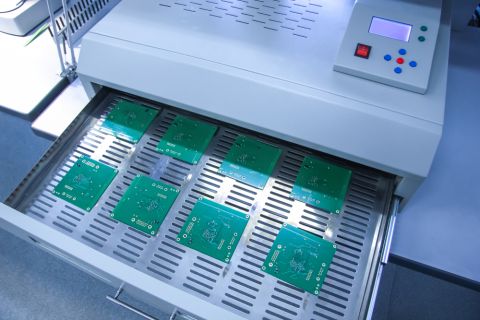
Drilling via holes in a PCB
Reliability Under Thermal Cycling
As a PCB is thermally cycled over time, volumetric expansion creates compressive or tensile stress on the copper wrap plating, via fill material, and laminate interfaces. The amount of stress depends on a number of factors, including the temperature gradient between the board and the environment, the thermal expansion coefficients for each material involved, and number of layers in the board.
Mismatched thermal expansion coefficients for the board materials is a cause of significant stress on copper wrap plating. This can cause the plating in the via barrel to crack and separate from the butt joint. Continuous copper wrap plating can also crack at the right angle at the end of the via.
Once the interior of the via separates from the butt joint, or if the via cracks at the edge of the wrap plating, an open circuit failure occurs in the via. More failures will occur as the flexes during repeated thermal cycling. Vias that end closer to the outermost layer in the board are much more likely to fracture under thermal cycling as the board will naturally flex to a greater degree in these layers.
Despite the potential for failure in these structures, copper wrap plating is still more reliable than vias that do not use copper wrap plating. This extra layer of wrapped copper provides extra structural integrity to the plating in the via wall, as well as increasing the contact area between the via plating and the annular ring.
Visibility and stability of the copper on your board is valuable.
The structural integrity can be increased further by adding button plating over the top of the wrap plating. Some manufacturers do this out of principle. The button plating will also wrap over the top and bottom edges of the via, just like wrap plating. The plating resist is then stripped, the via is filled with an epoxy, and the surface is finally planarized, leaving a smooth surface. This is arguably the best way to maximize reliability while still meeting the IPC 6012E standards.
IPC 6012E compliant plating can also be easily applied to buried vias, as long as the buried vias are segmented into separate layer stacks. The inner layer stacks can be plated with copper wrap, just as in the case of a through-hole via. These vias on interior layers can be plated just as one would do with a through-hole via. Each segmented stack is plated, the final stackup can be arranged using a prepreg.
Moving a Design to Fabrication and Manufacturing
When sending your circuit board out for fabrication and manufacturing, you’ll want to make sure you have the software available to accurately convey your circuit board and parts information accurately. Your design process shouldn’t be interrupted by having to re-source a supplier or find a new fabricator who can work with your exact instructions.
Using a good bill of materials can enable you to have clear part instructions to your partners and vendors. Having a design software which pairs with manufacturing output files and bill of materials can make it so that your design can get through to fabrication with ease and accuracy.
Great PCB design software like Altium Designer makes it easy to define your layer stackup, plating options, and design the vias that will appear in your multilayer PCB. A high quality PCB design software package like Altium Designer can help you design devices that meet the IPC standards.
If you are interested in learning more about Altium Designer, talk to an Altium expert today.
Related Resources


Related Technical Documentation


Connect design data and requirements for faster design with fewer errors
Request access to Altium 365 Requirements Manager!
Accelerate your design process for faster time to market
Analyze requirement change impact for thorough resolution
Automate risk assessment and compliance
Efficiently reuse requirements, components, and connections
Create accountability and reduce intent miscommunication
Request Access
Thank you, you are now subscribed to updates.