What is Lenz's Law or Simulation and How Does it Affect PCB Design?
Table of Contents

Lenz's law is one of the fundamental physical laws that describes the multitude of relationships between electricity and magnetism. Together with Ampere's law, Gauss law, Faraday's law, Coulomb's law, and the Lorentz force law, we have everything we need to understand the classical behavior of the electromagnetic field. Among these laws, Lenz's law and Faraday's law work together to describe how the magnetic field in your PCB is related to the electric current in conductors.
So what does it mean for your PCB layout? When it's clear how Lenz's law works, you can better understand how crosstalk and EMI will affect your design, as well as how inductors influence your design generally. Let's look at what exactly Lenz's law means for your design and how it governs signal behavior.
What is Lenz's Law?
In case you need a refresher on your physics fundamentals, it's important to remember that Lenz's law is the only effect in electromagnetism that doesn't have its own equation. Lenz's law is related to Faraday's law of induction, which relates the magnetic field passing through a coil to the voltage induced in a coil. In particular, Faraday's law states that the magnitude of the electromotive force (EMF, also known as voltage) induced in a coil of wire is proportional to the rate of change in magnetic flux passing into the coil:
![]()
Faraday's law doesn't say anything about how a change in the magnetic flux entering the coil is produced. The coil could rotate (such as in a motor or generator), the area of the coil enclosing the magnetic field could stretch or compress, or the magnitude/direction of the magnetic field could change. All of these effects would produce a change in the magnetic flux passing into the coil, causing generation of an EMF.
If you look at the above equation, you'll notice a negative sign. Lenz's law is the reason we put a negative sign in the above equation. In essence, Lenz's law tells you the induced EMF has polarity that produces a current whose magnetic field opposes the change which produces it when the magnetic flux is increasing. When the magnetic flux is decreasing, the induced EMF has opposite polarity. For this reason, we call the EMF a "back EMF", i.e., it points opposite the direction given by the right-hand rule.
Visualizing with Two Coils
The purpose of the negative sign shown above is easier to see when we think about how a current in one coil can induce a current another coil. Consider two coils A and B, as shown in the diagram below. Coil A carries a current that generates its own magnetic field according to Ampere's law. If the current is steadily increasing over time, the magnetic field and magnetic flux will increase over time, so there will be an increasing flux incident on coil B. Lenz's law says that the EMF and resulting current induced in the coil point opposite the direction given by the right-hand rule.
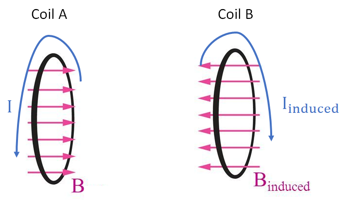
In other words, the induced voltage/current in coil B point opposite the inducing voltage/current in coil A when the magnetic field generated by coil A is increasing. When the field is decreasing, the voltages/currents point in the same direction. The induced current in coil B creates its own magnetic field, which opposes the inducing field created in coil A. This is the basis of induction motor drives as there will be a force between the two coils.
Visualizing with Magnets
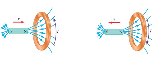
Another common way to visualize Lenz's law is to look at the current induced in a coil by moving magnets. The diagram below shows what happens when we move a magnet towards and away from a coil of wire. If we move the magnet towards the coil, the magnetic flux will be increasing, so a back EMF will be generated. This causes any current and EMF in the coil to point opposite the right-hand rule. However, if we move the magnet away from the coil, the right-hand side of Faraday's law will be positive! This means the direction of the induced EMF and current to follow the right-hand rule.
Diagrams with coils and magnets are great, but this all has to be related back to a PCB. The interaction between the magnetic field and current in your board is what governs the behavior of inductors, and it influences how signals propagate on traces and transmission lines.
Lenz's Law, Back EMF, and Inductor Coil
When we look at circuits, Lenz's law manifests itself in inductors and transformers. The simplest inductive circuit to consider when examining back EMF and Lenz's law is a series circuit with a DC voltage source, a switch, and an inductor.
The schematic below shows what happens when the switch in this circuit is closed. At the moment the switch is closed the current very quickly increases from 0 A to its steady-state value. During this time where the current rushes into the circuit, the magnetic flux on the inductor is increasing. For this reason, back EMF has the polarity shown below due to Lenz's law.
When the switch is opened, the current now drops from its initial value back down to zero. Therefore, the field in the inductor is decreasing over time because the current is decreasing. According to the negative sign in Faraday's law, the back EMF will now point in the same direction as the current in the inductor.

What happens in between opening and closing the switch? Since we are considering a DC current, nothing will happen when the DC current is constant because the current, and thus the magnetic field in the inductor, are not changing. Therefore, the back EMF will be zero. A back EMF is only generated when the current in the inductor is changing. This is why, when you look at the impedance of an inductor, the impedance is proportional to the frequency of the current in the inductor. When the field changes rapidly, the back EMF will be larger, so there will be greater opposition to current in the inductor.
Example: Back EMF in a Relay Circuit
While back EMF can be the driving force of DC motors, it can also be the menace that causes multiple problems on a PCB. Another inductive electromechanical element on some PCB designs is a mechanical relay.
Energizing a mechanical relay is generally harmless, but if the relay opens, the rapidly decreasing current in the relay coil will generate a large back EMF, which then cause arcing across the relay terminals. This can then propagate an ESD event into other circuitry. As an example of how this affects other components on a PCB, microcontrollers may experience a hard reset each time a relay is released, or the back EMF may introduce large enough current in reverse polarity to damage immediate components.
The following circuit diagram shows a mechanical relay with a flyback diode after the switch has been thrown (opened). The standard way to suppress current flow when a back EMF is induced in such a relay circuit is to use a flyback diode. This is done by placing a diode across the inductive coil such that it will be driven in reverse bias when the coil is energized.

When the relay opens, the current in the coil begins dropping and the coil de-energizes; the only closed path for current is for it to flow through the flyback diode, which becomes forward biased. This provides a closed path that allows safe discharge without allowing current to affect other nearby components. After the switch is thrown, the current decreases and a back EMF is induced in the inductive coil of the relay, which points towards ground. the only closed path for current in the circuit is through the flyback diode.
Back EMF can also cause arcing on the relay if you’re connecting a DC motor to open contacts of the relay. As DC motors are made of inductive coils, the same theory of Lenz Law applies when it is disconnected. As the back EMF attempts to maintain the decreasing current, a high reverse potential may cause arcing over the gap of the relay contact.
With reliable PCB design software like Altium Designer®, you can use integrated circuit design and simulation tools to understand what is Lenz's law and how it governs circuit behavior. If you’re dealing with issues related to EMF or want to learn more about the effects of Lenz Law on your PCB design, talk to an Altium expert.
Related Resources


Related Technical Documentation


Take advantage of the world's
most trusted PCB design system.
One interface. One data
model. Endless possibilities.
Effortlessly collaborate with
mechanical designers.
The world's most trusted
PCB design platform
Best in class interactive
routing
View License Options
Thank you, you are now subscribed to updates.