Parts Stress and Derating: Thermal Analysis & Electrical Stress Derating Integrated in Altium Designer
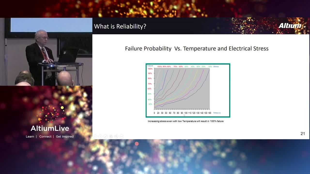
Table of Contents
<ul><li class="b-hide__item"><a href="#view-the-presentation-slides">View the presentation slides: </a></li></ul>
Imagine that you are at a ski site and you seat on a ski lift, which can carry a max of 60kg according to the manufacturer specification while your weight is 66kg. That is only 10% above the maximum allowed weight. Will you worry? Of course.
A good ski lift designer will use a safety factor and will design it several times stronger which can hold for example, 300Kg taking into account the possible weight of the skiers.
In electronics it is the same, if the designer uses components up to the max rating from the manufacturer datasheet, the components operation life will be shortened. Things are even worse if the temperature increases, the safety factor should be higher. This safety factor is called Derating.
Derating includes Power, Voltage, Current and Temperature parameters and they are calculated in DC and AC in average and peak modes. Every component is derated for different parameters, for example, Transistors: Power Dissipation, Collector Current, Breakdown Voltage and Junction temperature. This requires to set up all possible operational states for every component and to calculate the stress in the worst scenario. For example: Power dissipation and Collector Current when the transistor is in saturation and Vceo in cutoff mode.
Products reliability and life span depends on electrical stress and temperature. The average accepted stress is 50% at 25°C, above 25°C the derated stress level decreases to 0% at 125°C. An increase of 10% in stress or 10°C in temperature shortens the life by half. This important factor must be covered by the designer at the schematic stage to provide first class reliable product with a long life. This will also reduces the amount of failures in qualification and integration testing.
In this presentation, we will explain how different levels of Derating depend on the application, industry and environment, how to use the Altium Designer schematic data for thermal and stress derating analysis and how the results are shown on the schematic while over stressed components are colored in red.
View the presentation slides:
Sign up to pre-register for AltiumLive next year or try Altium Designer today.
About Author
Related Resources

Take advantage of the world's
most trusted PCB design system.
One interface. One data
model. Endless possibilities.
Effortlessly collaborate with
mechanical designers.
The world's most trusted
PCB design platform
Best in class interactive
routing
View License Options
Thank you, you are now subscribed to updates.