Editing Your PCB Geometry with MCAD Tools
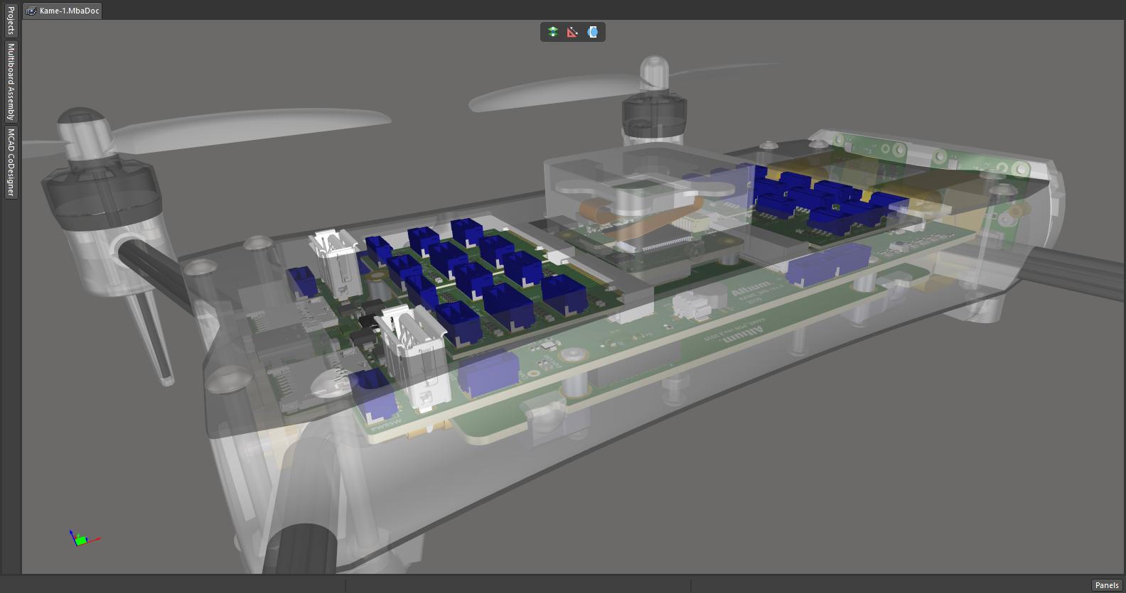
You need to define your PCB geometry in the context of your enclosure. If your board cannot physically be assembled into the final product, it doesn't matter how well laid out it is electrically.
This webinar focuses on how the MCAD CoDesigner allows you to edit your PCB in the context of a higher-level assembly, allowing you to respect the relevant mechanical constraints. Topics covered include:
- Defining the board outline geometry in MCAD software
- Creating board cutouts and mounting holes in MCAD software
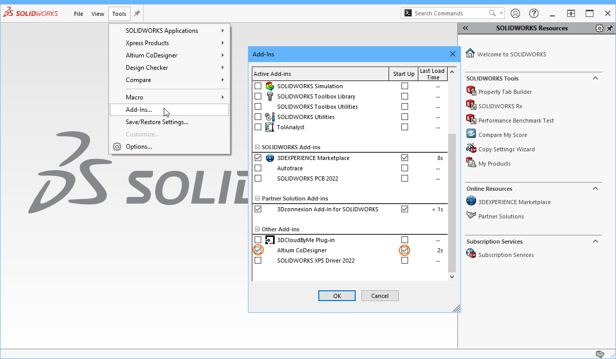
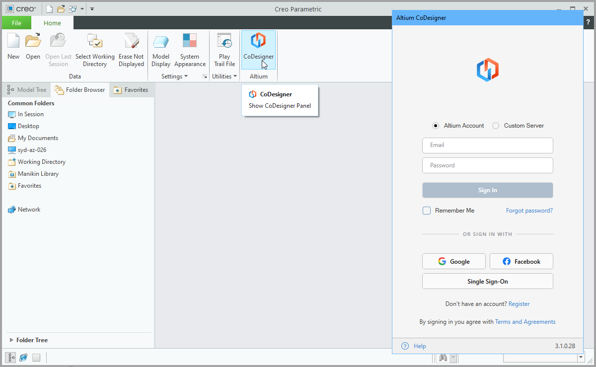
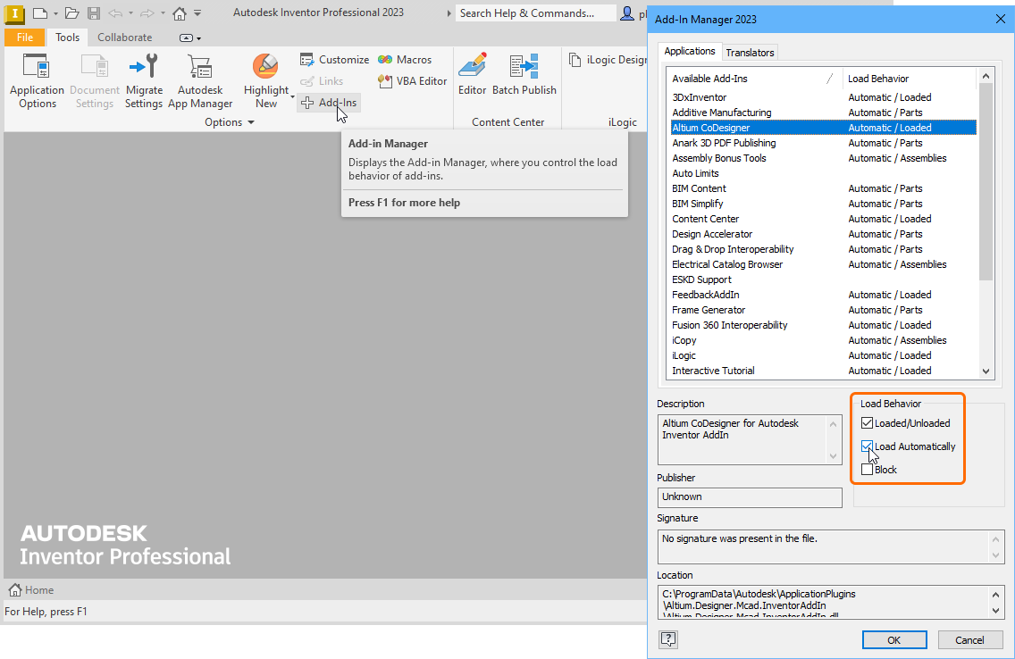
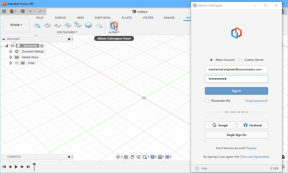
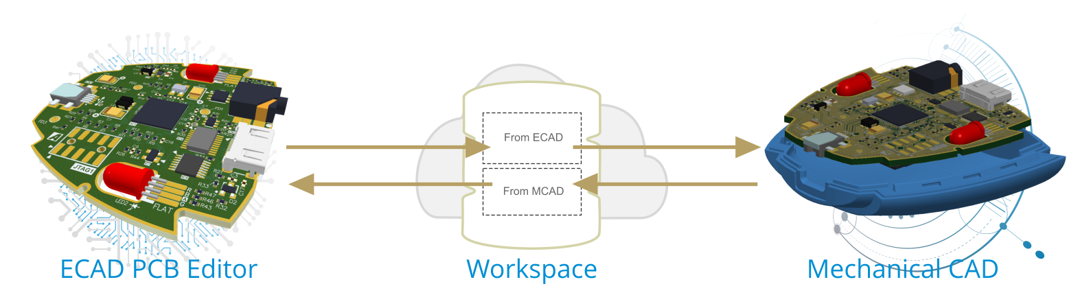
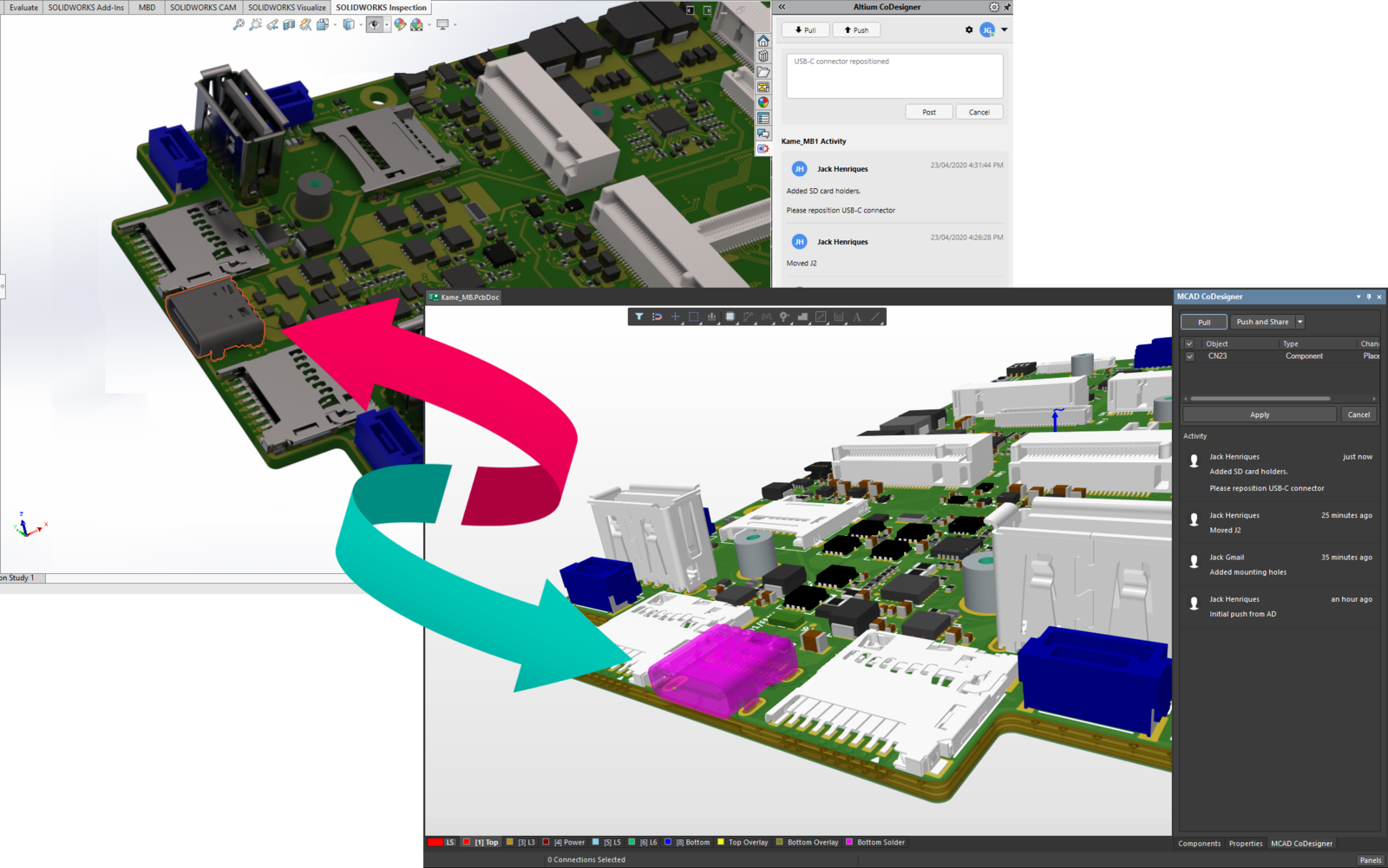
- Bi-directional design data transfer between Altium Designer and MCAD software
- Change history traceability with commenting, author, and time tracking.
About Author
Related Resources

Related Technical Documentation

Take advantage of the world's
most trusted PCB design system.
One interface. One data
model. Endless possibilities.
Effortlessly collaborate with
mechanical designers.
The world's most trusted
PCB design platform
Best in class interactive
routing
View License Options