ODB++ vs. Gerber X2 vs. IPC-2581: PCB Production File Format Wars

There's been a lot of excitement among PCB Designers and Fabricators over the last year about new PCB design and manufacturing hand-off. People tend to fall into one of four camps: Stay with Gerber RX-274X (the status quo), stay with / switch to ODB++ (Mentor's format), adopt the upgraded Gerber X2, or adopt the new IPC-2581 standard. No matter which camp you fall into, one things really clear - most of the scrap, wasted time, and manufacturing bottlenecks associated with design-to-fab NPI can be eliminated by adopting a new approach. Read on to find a bit about why IPC-2581 and Gerber X2 promise to solve these problems.
“Wenn Zwei sich streiten, freut sich der Dritte” - When two are fighting, the third is happy.
Many of us recently have been following an interesting “battle” between Ucamco’s Karel Tavernier and Mentor Graphics’ Julian Coates about which format is better: on Karel’s side is Gerber, and more importantly the recently updated standard Gerber X2 versus the more mature ODB++ which was originally developed by Valor, later acquired by Mentor Graphics. It’s worth mentioning that Julian Coates (Mentor) has made some effort to keep ODB++ open to combat fear of monopoly, and has actually done quite a good job of it - yet adoption of ODB++ in industry can be viewed as nothing short of pathetic. Is this really because of it’s potential monopoly support or because it’s lacking in some way? For background, the article(s) I am referring to can be found here.
While there has been much debate in the PCB industry over the past few years about new file formats for sending board designs to fabricators, one thing is absolutely clear - the old RS-274x (“Gerber”) is no longer adequate. Meanwhile, IPC2581 consortium members are diligently marketing this new format which promises to solve the same problems when comparing ODB++ vs Gerber PCB format, and like Gerber X2 in an open industry-owned standard.
...but why all the fuss?
There’s Trouble
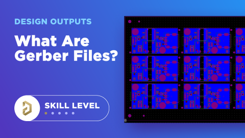
The old “Gerber files” standard is mature (30+ years old) and is accepted by all but the most primitive board fabricators. But it suffers from significant limitations among ocb designers. Anyone who’s had a few years experience getting boards fabbed with RS-274X has encountered delays to production because drills were missing or not aligned, or the board fab did not understand your Gerber file extensions and had to have you rename files to suit their wants, or at worst received boards that had layers out of their correct order.
It’s good to number the copper layers in the board so you can check after fab. In the above cover image, you can see layers marked with numbers. Another common practice is to place the name of the layer as text below the board outline in the PCB editor. The layer name in the image below is placed as a copper element. This will cause it to appear in the Gerber export outside of the board outline. CAM can then delete this or move it when they create a panel.

...but I have to say this is a clear indicator that the way we communicate designs to fabricators is seriously flawed. And, practices like this, while they are very good, are really workarounds to missing information in the file formats we have traditionally used for data hand-off. I would even go as far as to say fabrication drawings - in theory - should not be necessary (gasp!). Yeah, I said it.
Just a few of the serious limitations of RS-274x as it’s commonly used are:
- A separate physical file is needed for each layer of PCB information (i.e., copper images, fabrication notes, assembly drawing layer etc.)
- The layer stack is not defined - it must be manually communicated to the fabricator by way of diagrams, file names, and text documentation.
- It does not include drill information - that has to be sent in a separate “NC Drill” file, which is often mistakenly generated to a different scale or offset than the Gerbers file format.
- It contains no electrical connectivity information (netlist) so it requires a separate net list file to be sent for electrical bare board testing - again which may not necessarily match the Gerbers.
- It contains no component placement or bill of materials information - for pick-and-place and procurement separate files must be generated. This causes additional delay and problems for turn-key manufacturers that do both bare board fabrication as well as final assembly.
IPC-2581 and Gerber X2 Output Generators
IPC-2581 is a new standard from the IPC (International Printed Circuit association). Altium is a member of the IPC-2581 consortium, and will soon support generation of fabrication data to the IPC-2581B specification from Altium Designer®. The beauty of IPC-2581 is that it generates a single XML file which is capable of including all information needed to fabricate and assemble the printed board assembly - whether you’re just doing a bare board or the entire manufacturing process including pick-and-place and final test. IPC-2581 files include:
- Copper image information for etching PCB layers.
- Board layer stack information (including rigid and flexible sections).
- Netlist for bare board testing and in-circuit testing.
- Components Bill-of-Materials for purchasing and assembly (pick-and-place).
- Fabrication and Assembly notes and parameters.
Using this new standard means only a single file needs to be sent to the fabricator, without drill files, printouts, PDFs or even fab and assembly drawings - all the information needed to make the board is described within the IPC-2581 XML database.
Gerber X2
While it is an extension of the existing Gerber RS-274X standard, Gerber X2 provides some of the same benefits as IPC-2581, by adding the information that was missing - such as layer stack definitions, pad and via attributes, impedance controlled tracks - into original Gerbers in a backwards-compatible set of Gerber files. Netlists for testing, drills and other outputs can still be sent to manufacturers in their respective file formats. In this way, Gerber X2 provides an improved manufacturing output format that is backwards compatible with existing workflows, software, and fabrication equipment. It is therefore going to be a preferred choice for users who take a more conservative upgrade approach.
ODB++ Overview
One of the newer, more intelligent data formats is ODB++. This CAD-to-CAM data exchange format includes everything you would find in the classic Gerber format, as well as additional data that would normally be exported alongside the Gerber package. The ODB++ package contains three sets of files:
- ODB++ design files
- ODB++ process
- ODB++ manufacturing
In the Gerber format, a pad that you place in a PCB layout appears as a filled-in region in a Gerber viewer. There is no way to distinguish a rectangular pad that is used to mount an SMD component from a simple rectangular piece of copper that has no relation to a component (e.g., a testpoint). That information is stored in a different design output file (the netlist).
In the ODB++ format, pads for components are explicitly defined as pads within the output file package. When you export ODB++ files, everything is exported into a single ZIP file, and this is sent to the manufacturer. You don't export the various files in the above list individually, they are all contained in the same package. Some manufacturers encourage the use of ODB++ exports because everything is contained in one archive.
Time to Make Progress
Either way, the industry must move forward, and which output you choose will largely depend on your fabricator.
In Europe and North America, PCB fabricators are urging designers to use newer intelligent formats, because the NRE costs of using a “plain old Gerber viewer” for a PCB design review are really high. Any fab that has up-to-date CAM software can now support IPC-2581, ODB++, and Gerber X2, so there’s really no excuse. All the fabs I have spoken to about this agree - Sierra, Hughes, Precision…
But I’d like to know your thoughts - would you take the more conservative route (pardon the pun) of sticking with Gerber, or go with IPC-2581? If you chose the newer format, what steps would you take with your fab to guarantee the correct manufacture of your boards?
Once you’ve finished your PCB layout and you’ve completed a thorough design review, it’s easy to generate PCB design output files for your design in Altium Designer®. The OutJob file feature lets you create manufacturing file templates for your projects and quickly generate groups of files from your PCB layout and schematic data. When you’re ready to release these files to your manufacturer, the Altium 365™ platform makes it easy to collaborate and share your projects.
We have only scratched the surface of what’s possible with Altium Designer on Altium 365. Start your free trial of Altium Designer + Altium 365 today.
