3D PCB Design: Why You Need It and How It Will Help You
The other day I watched as a young father was entertaining his one-year old son on his shoulders. Securely held by his dad, the boy would constantly move from side trying to get different views of his father. In an overload of cuteness, he would first look at his dad over the left side of his face, then play with his hair, move over to the right side, then go back to where he started from.
I thoroughly enjoyed watching this precious moment, but it also brought to mind an important point. The child wanted every possible different view of his father that he could get, and so he constantly changed his perspective. As PCB designers, we also want to see every possible view of our designs. In the past, that perspective was constrained to working in a 2D CAD environment. However, now that 3D design environments are becoming more accessible, we should use these tools to help advance our designs.
A 3D view of a PCB design has many benefits for the .
Old school design in 2D and Benefits of 3D
When I first started out as a PCB I worked for a company that made display devices. This was still “back-in-the-day” when we were using UNIX based CAD systems that only provided a 2D working environment. One of my first designs was sent over to the mechanical CAD group where they rendered it in 3D for me. Even though it was only represented by primitive block shapes, I was still amazed at how my design looked in 3D. It was the first time that I had ever seen one of my designs like this and the memory of that moment has stayed with me. Working in a 3D environment can offer a lot of benefits to the PCB , here are a few of them.
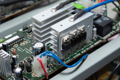
3D Component Footprints: One of the first things that I noticed in looking at that design in 3D was that I had a large electrolytic capacitor sticking up through the case of the device. This should have been caught by my DRC’s, but for some reason, it wasn’t. Therefore it was a real surprise to me to see it waving out the back end of the device like the tail of a dog. In today’s CAD systems, setting up your DRC’s for catching these types of errors is a standard feature. Now with the ability to work in 3D, you will have real-time feedback for exactly how the heights of your components will look like.
Visualizing Layer Structures: PCB designers can benefit from being able to see exactly how a board layer structure looks in 3D. The can tilt, rotate, pan and zoom the image to see what a via stack will look like and exactly how it is interacting with the other objects around it.
Full 3D Editing Capabilities: Viewing our designs in 3D is just the beginning since the layout can also be edited in the 3D mode. The PCB is able to interactively ascend or descend through the board stack-up in order move , push traces, or route onto another layer.
MCAD/ECAD Collaboration: A 3D CAD system will also give you the ability to add a mechanical object to the design, such as the device case. With this functionality, you will be able to view the 3D components in relation to the case, or other mechanical objects, and run 3D clearance checks on these elements.
Flex Circuits: Another benefit to working in 3D is in designing flex circuits. With a full 3D environment you will now have the ability to view the finished flex circuit folded up as it will be when assembled. Imagine that; you no longer have to guess how your flex design will look when it is in use as you can use your 3D CAD system to give you an exact representation. This allows you to see assembly and clearance problems that may arise with the design in its final folded configuration before going to the manufacturer. By finding the problems first in your 3D CAD system, you will reduce the need for additional board spins to work out mechanical issues and ultimately save money.
Working in a 3D environment will help PCB designers leverage the full potential of their design tools.
3D Design: The New Standard for Today’s Design Requirements
Traditionally, PCB designers have been constrained to working within a 2D environment. Although this standard has worked for many years, today, PCB design is evolving quickly. Emerging technologies, such as wearable devices and the IoT, are moving the design industry towards the need to work within 3D. With the competitive need to get the design to market first, PCB designs can no longer afford the luxury of multiple board spins to work out manufacturing difficulties. Mechanical clearances, flex assembly details, and component spacing problems can all be preemptively resolved before going to manufacturing by designing the board within a 3D environment.
Just like that little boy explored every possible perspective in order to get a better view of his dad, we also have the ability with 3D to explore every perspective of our designs. The potential for a whole new way of designing boards is right here in front of us, we just have to dive in. Using 3D PCB design software, like Altium Designer® , is an excellent way to get started.
Want the full picture of how 3D can help your designs? Then talk to our 3D design environment experts at Altium.


