


Assembly Tips and Tricks

At a Glance
Master the art of PCB assembly with expert tips and techniques tailored for hand assembly. From stencil selection to reflow processes, optimize your assembly workflow for efficient verification whether for prototyping or mass production.


After you've finalized your PCB design in Altium and the PCBs have arrived, it's time to think about how to assemble the boards for verification. Whether for mass production or prototyping purposes, a designer should be aware of assembly techniques. It should be part of the design review process to ensure the board has been checked against Design-for-Assembly (DFA) issues. This article's main focus will be hand assembly, so I'll share various tips and tricks from my experience, such as stencil and solder paste selection, temperature delta challenges, component soldering, etc.
Create a Solder Paste Stencil
First and foremost, using a stencil to spread the solder paste is a huge time saver compared to dispensing it with a syringe. Nearly all prototype circuit board fab houses worldwide offer ultra-cheap frameless stencils, or some companies offer standalone services to produce low-cost prototypes. That said, it is worth every penny not to hand-solder every single surface-mount component, and it's much easier at the same time.
Even though there are different processes or materials for stencil production, it's simply a matter of having solder land apertures on a thin metal sheet, generally stainless steel. Depending on the minimum pitch size in the artwork, chemically-etched or laser-cut stencils might be used. Chemically etched is optimal if your design has very fine pitch components. The smallest pad sizes also drive the thickness of the sheet metal so that the correct aspect ratio might be preserved for the correct amount of solder paste disposal. Prototyping and low-batch production generally do not require a framework around the stencil unless you plan to use assembly machines, so going with a frameless stencil will reduce the cost.
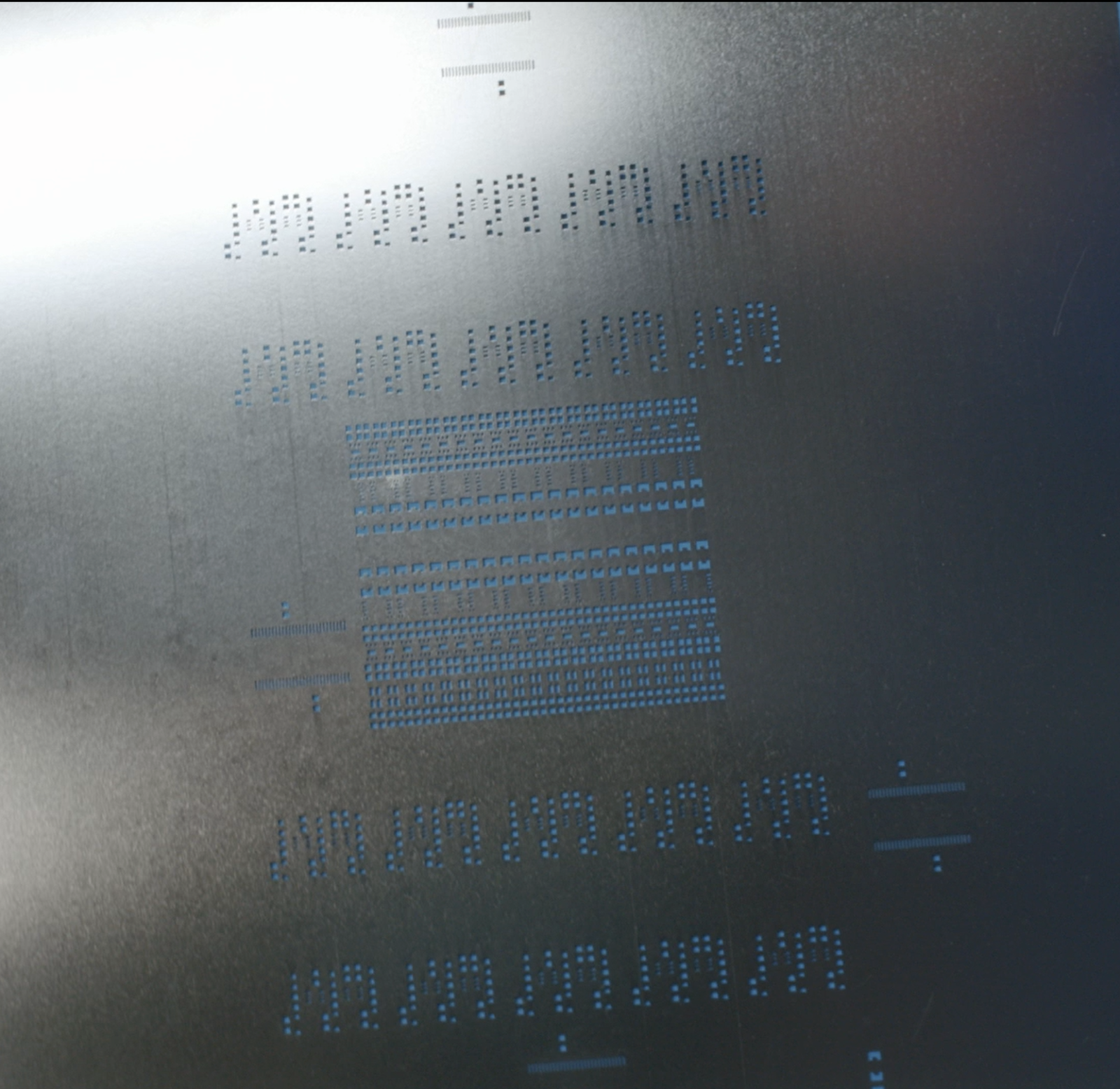
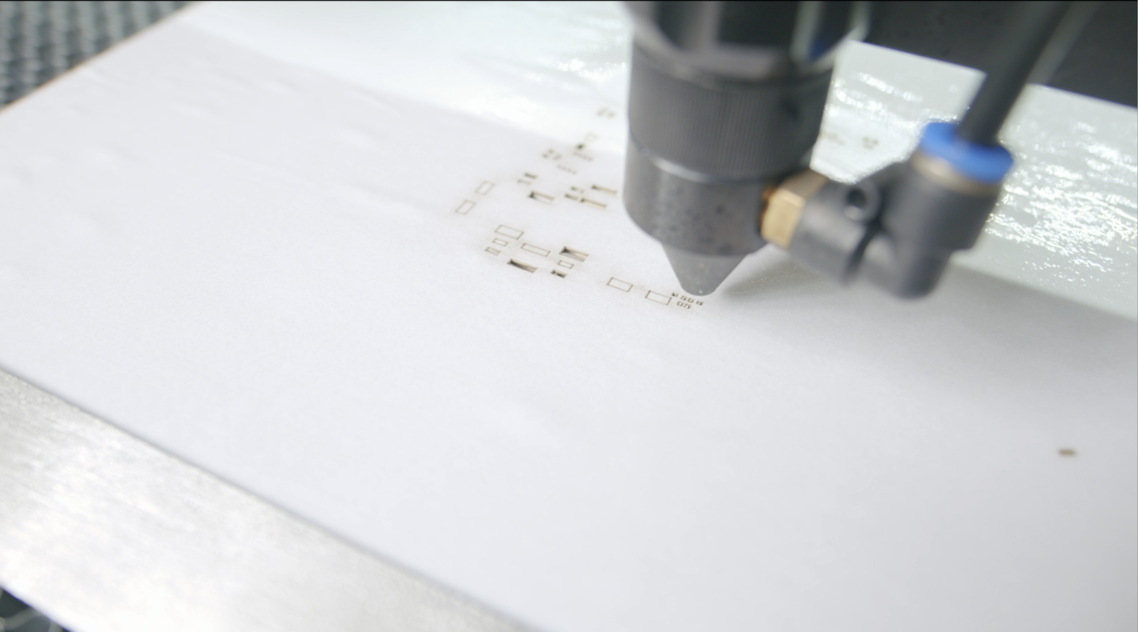
From a different perspective, if you're more into DIY and have access to a laser cutter, you can even produce a stencil from laser printer transparencies.
You might have tried to laser-cut a sheet. It might not have gone very well, resulting in a melted mess. However, this is where laser printer transparencies come into play, where the acetate sheets can handle higher temperatures and have about the right thickness. It's all about thermal management, and there are some tricks to improve the laser-cut operation of a stencil. First, since acetate sheets are lightweight, you don't want to cut directly on the laser bed as they might easily move during the process. My preferred solution is to use a flat section of cardboard box soaked in water for the first layer, which is covered with a sheet of regular copier paper also soaked in water. On top of this is added the transparency sheet and another sheet of copier paper soaked in water. One might think that's a lot of water to soak the stuff up, but a laser beam has no problem with water; on the contrary, it keeps everything nice and cool so that the stencil doesn't melt. You can decrease the air assistance to a minimum level that won't dry the paper and keeps the lens clean.
Keep your movement speed low unless you have a high-end machine such as Trotec or Epilog. Some lasers might bounce from the belts, resulting in imprecise corners and blowing out the small slivers between fine-pitch component pads. As a last setting, the power level should be set to cut the first layer of cardboard but not all the way through, ensuring you have enough power to cut cleanly without unnecessary heat.
Fixation and Paste Application
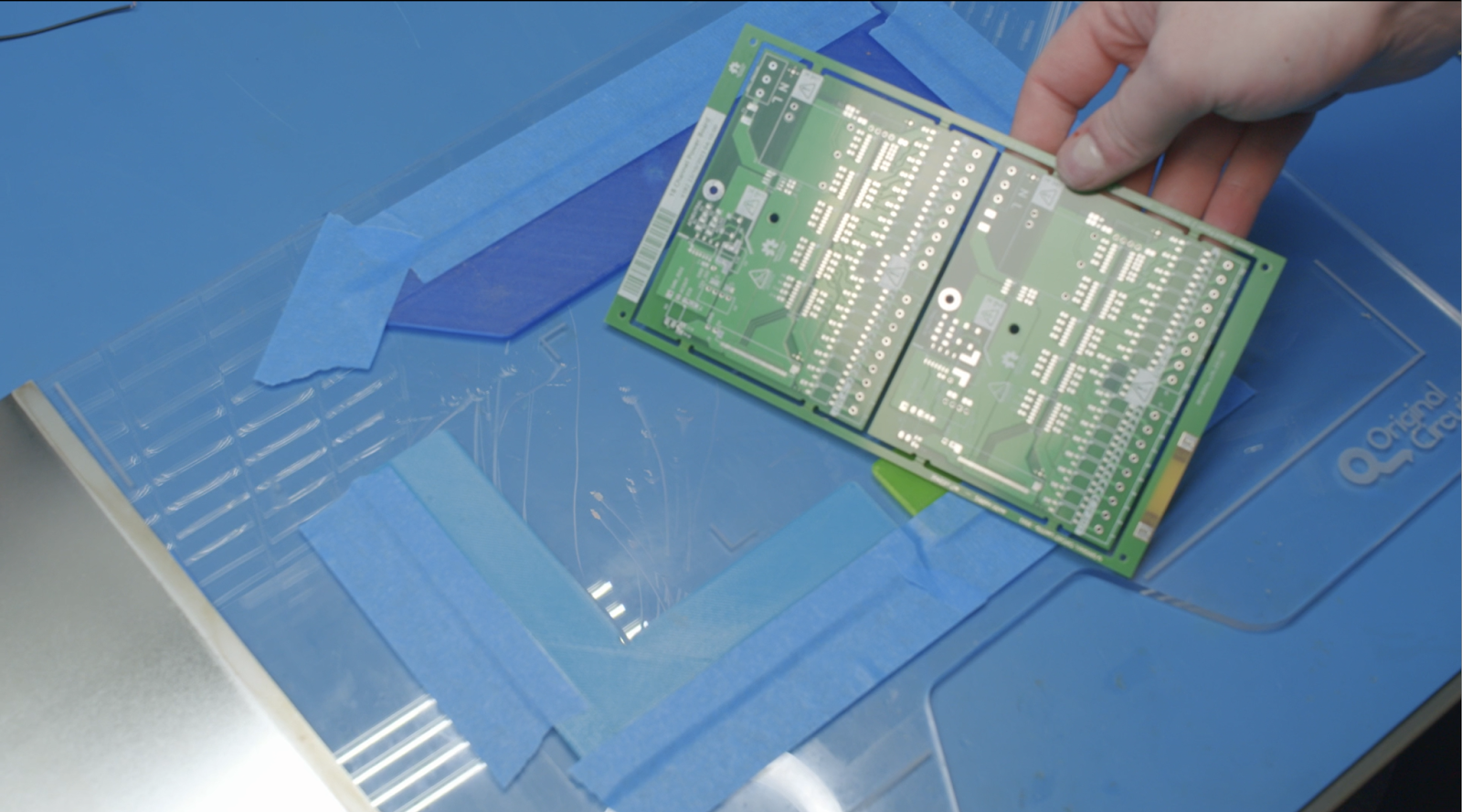
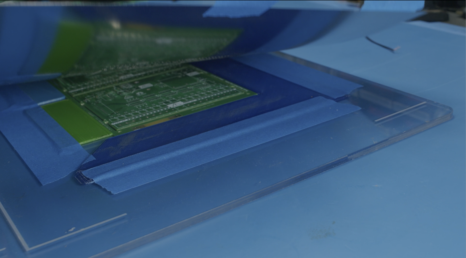
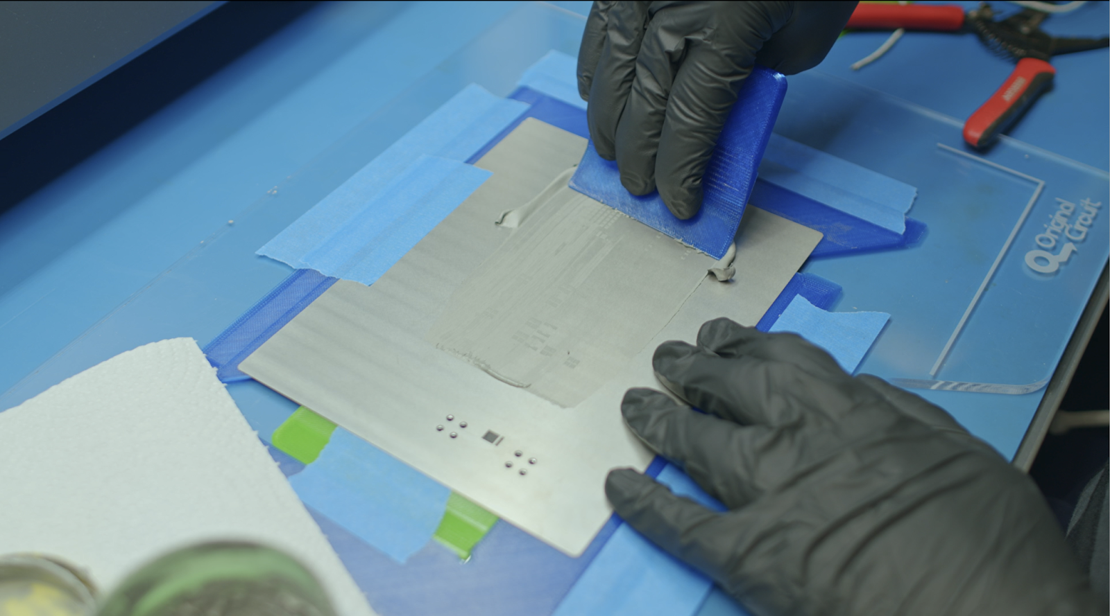
After you have the stencil, it's crucial to align it on top of the circuit board precisely. Taping extra circuit boards from old projects on my desk to form a frame was my go-to solution until I recently laser-cut an acrylic sheet to do my stenciling. It doesn't necessarily have to be a laser-cut surface, but anything rigid and flat, such as a clipboard or chopping board, should do the same job.
Instead of using leftover PCBs to hold the board on my acrylic sheet, I've also 3D-printed board surrounds with a lip that ensures the stencil doesn't sit on anything higher than the board surface. Having the stencil sit gently on the board's top surface will help reduce the smearing effect by keeping the board in contact with the board during the entire process. I've also found it useful to tape the stencil to another plastic riser that acts as a hinge, allowing us to lift it cleanly. Don't be afraid of using extra tape on the opposite edge of the stencil to prevent anything from shifting, as alignment during application is vital. There are plenty of ways to have accurate DIY alignment, especially after the 3D printer revolution, and this is only one of them.
The next step is applying the solder paste, but you should have the proper paste. I prefer using Henkel Loctite's GC10 series in T4 or T5 mesh size, where the finer the mesh, the better the application on small pads. This paste is perfect for prototyping for a couple of reasons. First, you'll have over 8 hours of assembly time before the paste goes bad. In addition, for it to be room temperature stable, it does not necessarily need to be stored in the refrigerator. Although good quality solder paste is expensive, a tub of it will serve you well beyond the end of its shelf life. Don't worry if the paste is expired - as a lifesaving hack, instead of throwing out expired paste which is hard to stencil, you can just add some gel flux to the paste. CHIPQUICK's SMD291 is far away the best choice for me over any other gel flux, and I can't think of a better duo other than expired paste mixed with expired flux.
Now that you have paste on all the pads, it's time to place the components. Curved tweezers are my favorite because they offer better visibility and precision while placing the components. Still, I strongly advise avoiding cheap multi-pack tweezers at all costs—they are not worth it. You're looking for stainless steel or ESD ceramic in a 7SA pattern. I also love to have padded grips, as they're much comfier during long assembly sessions.
Keep Track of Parts With Assembly Assistant
Printing out the assembly drawing is one option for tracking which part goes to where. I've recently tried the Assembly Assistant, available within Altium Develop and Altium Agile, which is way more practical than printouts. It's easy to follow assembly progress by virtual board population and search functions with good visual feedback. Click the link if you'd like to try it; you may not want to return to printouts.
Achieving Precision and Speed in Manual PCB Assembly
When you reflow the board, you get some help from surface tension, which gives you some freedom in placement precision. As long as the component terminals touch the paste, the part will straighten during the reflow, making your life easier when placing small components such as the 0201 package. When it comes to IC placement, just make sure terminals are lined up with the paste and do not touch an adjacent pad, then leave the rest to surface tension. There is no need to worry if it's not correctly placed during reflow, though; if you're unsure, give the IC a little nudge while the solder is still liquid, and it will bounce back to its location or pop out of alignment. You can pick it up and fit it again if it's out of alignment.
A simple temperature-controlled hot air rework station is generally suitable for reflowing most boards. The 858D-style rework station has served the purpose well for over a decade in my lab; it's cheap and does the job well enough. Just be aware that your bench and ESD mat might melt during reflow. I use pyramid-style silicone baking sheets to keep the board warm and isolate my bench top. You don't need to go to the expense of a toaster oven for a reflow; however, if you choose to check out picoReflow, which is an open-source project that takes control of your oven.
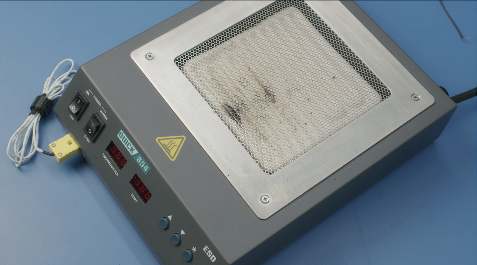
The reflow process might get slightly complicated if you have a board with a lot of thermal mass, such as metal cores or plenty of layers of heavy-weight copper. Getting enough heat into the board may take longer, causing your flux to evaporate before the solder is completely reflowed. You might need to consider using a preheater since the reflow station will not solely be enough. If you're up for the cost, JBC makes some of the best professional preheaters. I'm using the relatively low-cost alternative Quick 854, which has a limited heated area and control. Alternatively, a cheap electric skillet or Teppanyaki grill is a budget alternative for professional preheaters; however, they have poor heat control that alternates between overheating or not providing enough heat.
If your lab has a preheater, you can think about using it for the entire reflow process. Even though they're capable, I do not prefer using them for reflow. Instead, I'd like to use them to heat the board to the paste's soak temperature, then use my hot air station to heat the board selectively – one area at a time, which allows me to monitor the solder melt. Doing this also reduces my rework time for assembly issues since I can correct any issues on the go. It's not a complete replacement for a multi-zone industrial reflow oven. Yet, only a small percentage of my boards see issues like tombstoning or misaligned placement.
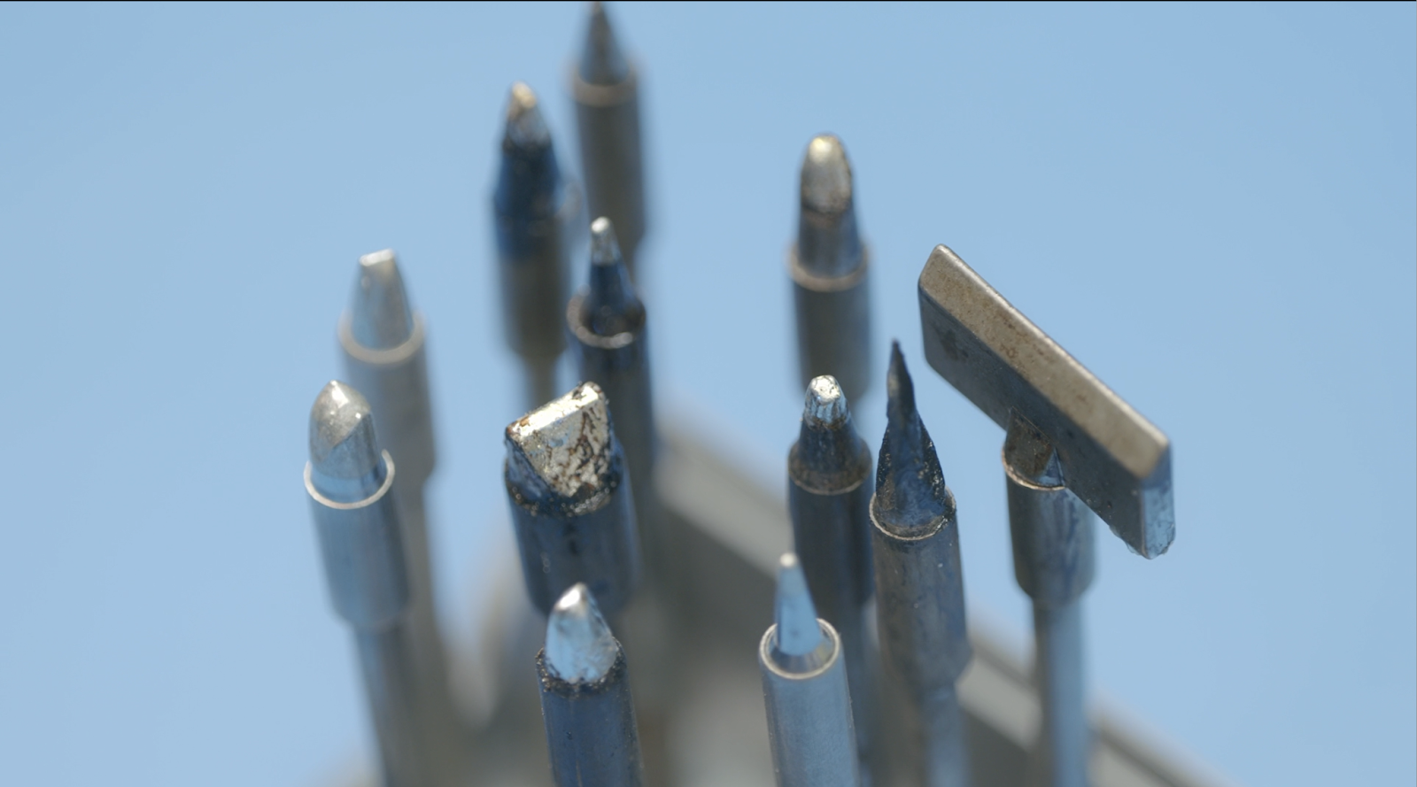
Through-hole parts are last in the assembly process. You should start thru-hole assembly as soon as the board has cooled down to handle, especially if your board has a lot of thermal mass. Working with the warm board will decrease the temperature delta and make your life easier during soldering. It's worth mentioning that a good quality soldering station will help you a lot, in addition to selecting the right tip geometry. I prefer chisel tips rather than conical ones, which are generally more painful than they are worth. If you have through-hole components with a lot of thermal mass (such as terminal blocks), heating the lead is more of a challenge than heating the board. Consider using a specialized tip with a concave section to handle those. It doesn't matter if the tip is bigger than the component or lead; surface tension will help you greatly. I happily use a 3mm wide tip to rework 0402 parts.
With all the tips and tricks, prototyping with surface-mount components would be far easier and faster than prototyping with through-hole parts. Try in-house prototyping; it doesn't take a lot of time as long as you keep the component count within manageable limits yourself. It's also kind of a meditation, and I find it quite relaxing. Follow up for more assembly tips for a huge number of components, pick-and-place assembly, and so on.
About Author
Related Resources
Related Technical Documentation
Table of Contents
Design to Release, Without the Friction
- Keep reviews tied to the right version
- Reduce handoff confusion and rework
- Spot sourcing and release risk earlier
- Work solo, share when needed
Get Started
Thank you, you are now subscribed to updates.

