


Como estas
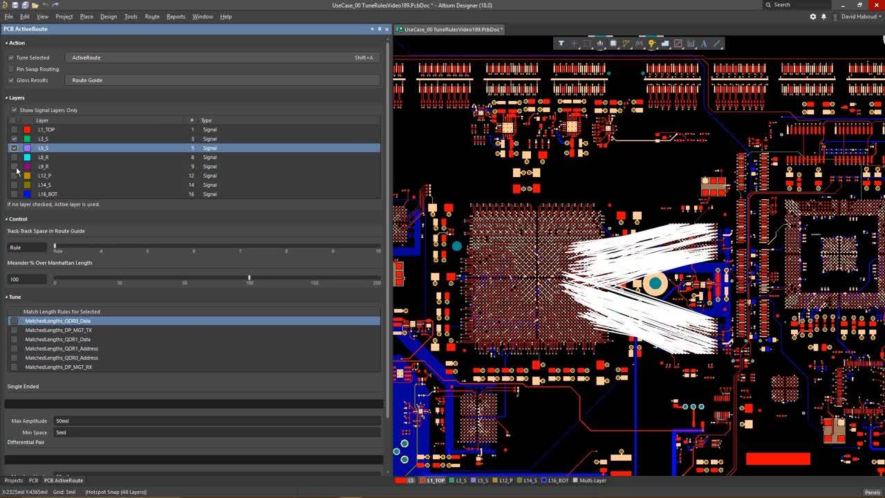
Las reglas de diseño de la categoría Manufacturing se describen a continuación. La categoría Manufacturing de reglas de diseño. Hecho - 26.6, en la versión Beta: deshabilitar Beta y empleado de Altium para el cuadro condicional de arriba, habilitar Beta y empleado de Altium para el cuadro condicional de abajo. Cuando PCB.Rules.RuleSets salga de la Beta cerrada, en la versión pública: eliminar el…
Altium CoDesigner es una interfaz para transferir diseños de placas de circuito impreso entre los entornos de diseño ECAD y MCAD. Los cambios de diseño se transmiten a través de un Altium Workspace, que actúa como puente entre los entornos ECAD y MCAD. Altium MCAD CoDesigner funciona con Onshape, una plataforma totalmente nativa en la nube de diseño asistido por computadora (CAD) y gestión de…
Software MCAD compatible Actualmente, se admiten las siguientes plataformas y versiones de MCAD: Autodesk Inventor Professional® Autodesk Fusion® (solo versión para Microsoft Windows. La licencia Autodesk Fusion Personal solo es compatible con Altium CircuitMaker) Dassault Systemes SOLIDWORKS® (Standard, Pro y Premium) PTC Creo Parametric® Siemens® NX™ - (para diseñadores con una Altium…
Cerrando la brecha entre ECAD y MCAD El producto electrónico que sostiene en la mano es la combinación de numerosos diseños independientes. En primer lugar, está la carcasa que está sosteniendo; dentro de ella habrá una o más placas de circuito electrónico y, en la placa, a menudo hay un microprocesador que ejecuta software. Más allá de eso, puede haber secciones especializadas de circuitería…
Parent page: Global Sharing In support of Altium 365's Global Sharing paradigm, Altium Designer supports the ability to share your design projects with others, anywhere around the world, directly from within the software. This complements the ability to share designs from within the browser-based Altium 365 platform itself. The following levels of sharing are supported from within Altium Designer…
Parent page: Finalizing the Board Design Via stitching is a technique used to tie together larger copper areas on different layers, in effect creating a strong vertical connection through the board structure, helping maintain a low impedance and short return loops. Via stitching can also be used to tie areas of copper that might otherwise be isolated from their net, to that net. In RF designs, to…
Working in 2D and 3D Layout Mode Historically, PCBs have been laid out in a two-dimensional design space that uses colors to represent the various layers of the PCB. However, the physical PCB is a three-dimensional object, which requires the PCB designer to take the multiple-layer, 2D representation on the screen and map that to a 3D representation in their mind. The substantial improvements in…
Cuando trabaje con un documento gráfico, como una hoja esquemática, un documento PCB o un documento de Draftsman, puede ampliar, reducir y desplazar el documento para centrarse en un área específica. Los atajos básicos que pueden utilizarse para hacerlo son: Ctrl+Mouse Wheel para ampliar y reducir Right-Click, Hold&Drag para desplazar el documento El menú principal View incluye una serie de…
Parent page: Board Design Release Publishing Destinations offer you the ability to publish release data for a revision of a PCB Fabrication Data Item, PCB Assembly Data Item, or PCB Project Design Item, directly from a managed content server, or Output Job, to a storage space - such as Box.com, Amazon S3, an FTP server, or a simple folder location on a shared network. This enables you to host…
Parent page: More about Schematics Related Resources Creating Connectivity Compiling and Verifying the Design Design Synchronization When schematics were originally captured on paper, it was often on a single sheet of paper large enough to fill a big drafting table, and reproduced by a dedicated large-format copier. Times have changed, now schematics are captured on a desktop PC, stored on a…