


7 Ways to Catch Rules & Constraints Early – Checklist


Every engineer who has encountered late DRC or DFM surprises during the design process knows how painful they can be. They can introduce delays, increase costs, and complicate an otherwise well-structured design. Altium Designer Agile helps you catch these issues early. This guide shares practical tips for identifying and mitigating risks before they become expensive rework.
✅ Standardizing rule sets
Creating standard rule sets helps ensure consistent outputs and improves manufacturability. Depending on the board class (which affects price and yield), different requirements will apply—such as copper width and spacing, clearances, minimum hole sizes, and signal integrity constraints (e.g., impedance control).
Preparing a rule set should be a collaboration between design engineers and manufacturing engineers at the facility where the product will be built. This prevents mismatches between factory capabilities and the constraints defined in your EDA tool. If you do not have a designated EMS partner yet, it is a good practice to follow international standards such as IPC-2221.
Standard rule sets can be reused across projects.
To reuse rule sets in Altium Designer Agile, go to Design » Rules, right-click anywhere in the list, and select Export Rules or Import Rules. If constraint management is enabled, go to Design » Constraint Manager, right-click the selected rules, and choose Export or Import.

Export menu in Constraint Manager
Export menu without constraint management
✅ Structuring constraints
Structuring PCB constraints helps organize rules into logical groups (e.g., net classes) and define limit values for object properties. There are several types of constraints:
- Physical - parameters such as trace width and spacing, clearances between copper objects (which may be defined as separate constraints), and via dimensions
- Electrical - properties that ensure correct electrical behavior, including signal topology, impedance control, length matching, layer sets, and via counts
- Fabrication - rules related to board fabrication, for example text size, silkscreen-to-silkscreen and silkscreen-to-solder mask clearances, solder mask openings, and hole characteristics
- Assembly - component clearances and placement orientations
Depending on the software, some properties may be presented as separate constraints, but they follow the same general idea.
In Altium Designer Agile’s Constraint Manager, the main constraint types are Clearances, Physical, and Electrical. Additional parameters are defined in rule classes such as High Speed, Manufacturing, Placement, and Signal Integrity.
To create constraints, select Design » Constraint Manager and set the desired values for all nets and net groups.
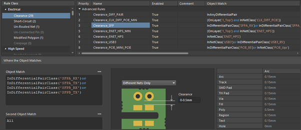
Setting desired clearances for nets in Constraint Manager
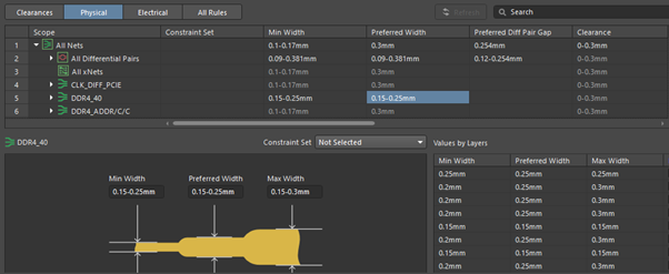
Setting desired track width for different nets in Constraint Manager
✅ Incremental validations
Whenever you make changes to a design, it is important to keep nets and connections consistent across the schematic, layout, and BOM. While compilation runs automatically in the background, applying changes requires creating and executing an ECO (Engineering Change Order). This often happens multiple times during a project, and engineers need to track any deviations. Performing routine checks helps ensure consistency across all project data.
To do this in Altium Designer Agile, run a project validation by choosing Project » Validate Project, and use the Messages panel to navigate Warnings and Errors.

Go to Project » Project Options » Error Reporting to select report modes
✅ Early DFM alignment
To identify and resolve issues early, keep your manufacturer involved and align on DFM requirements as soon as possible. Fabrication sites may provide engineering questions (EQs) in advance to avoid misunderstandings. Assembly engineers can verify footprints and pad designs, check component spacing and orientations, confirm fiducials, and validate board markings. After receiving feedback, you can implement changes in the design and update rule sets to prevent similar issues in future projects.
To share design files with collaborators and let them leave comments, choose Project » Share.
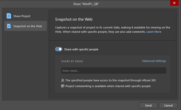
Share with specific people to allow them commenting on your design
✅ Preventing rule drift
Even with well-defined rules, large numbers of violations can appear during a final DRC -sometimes hundreds or even thousands. To avoid the time-consuming work of clearing them all at the end, follow these best practices to prevent rule drift:
- Use online DRC for continuous validation
- Check which rules apply to each object
- Set proper rule priorities, especially after adding new rules
- Re-enable rules that may have been disabled during design (e.g., Un-Routed Net, Net Antennae)
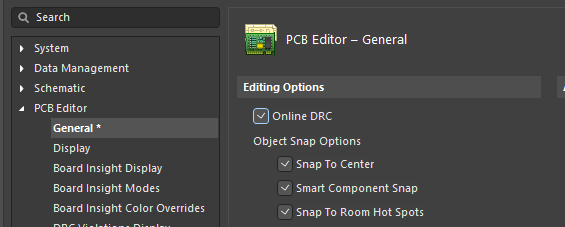
Enable online DRC in Altium Designer Agile Preferences
✅ Milestone DRC checks
After each milestone (for example, completing routing for a circuit), perform a batch DRC and clear violations before moving to the next stage. If issues accumulate until the end of the project, clearing them becomes time-consuming and increases the risk of missed errors. If some violations were waived, review them during each DRC run to ensure they are still relevant. Each time, verify that the DRC parameters are configured correctly.
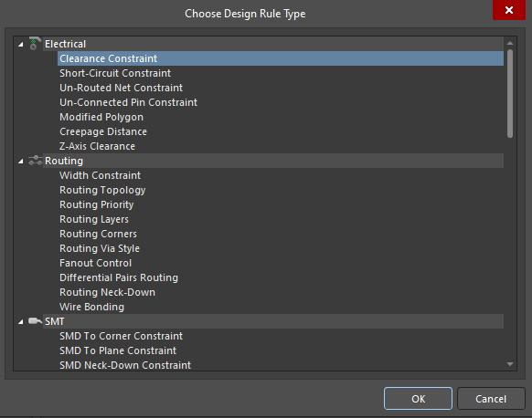
To run a DRC in Altium Designer Agile, go to Tools » Design Rule Check, select the rules to be checked, and click Run Design Rule Check.
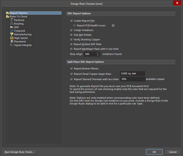
Design rule checker menu - on the left you can choose the rules being checked
✅ Permission discipline
When storing project files in a shared space, assign permissions carefully. Only design engineers and key project stakeholders should have edit rights to prevent unauthorized changes. For additional verification, check revision history to spot unexpected edits.
Altium Designer Agile helps you catch rules and constraint issues early and keep your PCB design process consistent. To learn more, visit our Agile Teams page and try the software free for 30 days.

About Author
Related Resources
Related Technical Documentation
Table of Contents
Design to Release, Without the Friction
- Keep reviews tied to the right version
- Reduce handoff confusion and rework
- Spot sourcing and release risk earlier
- Work solo, share when needed
Get Started
Thank you, you are now subscribed to updates.

