Migrating From Autodesk Eagle™ to Altium Designer®
 Open as PDF
For the purpose of this migration guide we are going to focus on importing Eagle PCB Designs, if you require other files migrated, please refer to their specific guide.
Preparing to Migrate Your Legacy Data
Never forget that migration of data follows the “garbage in…. more garbage out” principle. So, we need to consider four distinct phases of the process, this is best shown in the flow diagram below:

Step 1: Prepare Original Data - Pre-Translation Tidy Up
It is prudent to clean and tidy your design within your legacy system before trying to export. We’ve put together a checklist to help you:
- Schematic considerations
- Does this design have single pin components representing power objects?
- Connectors are represented as one-gate-per-pin with over 256 “gates”
- Keep a note of the ambiguous connectivity in the design (For example - multifunctional pins, hidden pins, or implicit connections).
- Make sure to understand which nets in the design are local(defined at the document level) in nature.
- Do the schematic symbols call up the correct PCB footprints?
- Does the schematic match the PCB?
- PCB considerations
- A large number of graphical objects like mechanical drawing or non-ECO-registered drawing primitives need to be assigned in the documentation layers.
- Make a note if the design has star point earth.
- Deliberate DRC violations (For example, allowed short circuits and net-ties).
- Objects extending beyond the environment
- Knowledge of correct PCB layer assignment is required in order to map the imported layers with existing layers in Altium Designer.
- Do the auto-named nets match with the schematic?
- Library considerations
- Schematic symbols matching with PCB footprints
- Correct supply chain information and BoM parameters
- Associated 3D models cannot be imported for eagle-based libraries and one can import the respective STEP models in Altium later on.
- Correct representation of custom pads, copper shapes, solder mask and resist.
Step 2: Save Data in a Suitable Format
Supported Version and File Formats
The following table details the versions of all Eagle design formats that can be migrated into Altium Designer. Note that this list is updated all of the time, so please check with us for specific systems and versions before undertaking migration.
|
|
|
|
|
|
|
|
|
|
|
|
|
|
|
Altium Designer's EAGLE Importer is able to import EAGLE design files saved with EAGLE version 6.4.0 (or later). These are XML-format in nature – EAGLE binary-format design files cannot be imported directly using the EAGLE Importer. For these older, binary version design files, it is advised to save them in this later (XML) format, through your EAGLE software, before attempting to import them into Altium Designer.
PCB files translate as follows:
- Eagle PCB Design files (*.brd) translate to Altium Designer PCB files (*.PcbDoc).
- Eagle SCH Design files (*.sch) translate to Altium Designer PCB files (*.SchDoc).
- Eagle Library Design Files (*.lbr) translate to Altium Designer PCB Libraries and Altium Designer Schematic Libraries (*.PcbLib & *.SchLib).
Step 3: Import Data into Altium
Using the Import Wizard for Eagle Design Files.
The Import Wizard can be launched from the Altium Designer File menu. Choose the EAGLE Projects and Designs from the list of file types as shown in the screenshot below. On the “Importing Eagle Design Files” screen, click the Add button to choose the Eagle design files. Multiple files can be translated at the same time. Step-by-step instructions on how to use the Import Wizard are to follow.


Step-by-Step Import Instructions on Importing Eagle Design files.
- Start the Import Wizard with File » Import Wizard

- Select Type of Files to Import » Eagle Projects and Design

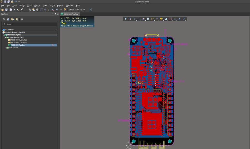
- Add the file(s) to be translated. In this case, ‘MKR1000.brd’ and ‘MKR1000.sch’ have been used.

Using the ‘Reporting Options’ page map the layers for the PCB by assigning a suitable layer type and layer name to be Signal/Solder/Paste/Silkscreen/Mechanical

- Use the 'Output Project Structure' page to enable or disable the settings for logging all errors, all warnings, and events respectively. You can also set up Schematic Settings here.

- A preview of the files being translated and their output directories are then shown. You can change the main output directory at this point if desired.

- Click the final Next button and the Import Wizard will take care of the rest.

- Congratulations, your design has now been imported into Altium Designer! Follow the Post Import Tidy Up checks to ensure the design has been fully checked and verified.

Step 4: Post Import Tidy Up
We’ve put together a verification checklist for you:
- Physical check
- View » Fit Document
- Board shape and cutouts
- Electrical check
- Netlist
- Rules
- Have all rules been imported
- DRC check
- Check settings for polygons - Island removal, min primitive size
- Thermal reliefs, direct connect
- Check power plane settings
- Power plane Pull-back
- Solder mask, Paste mask rules
- Via Tenting
- Testpoint assignments
- Power check
- Nets
- Planes
- Polygons
- Documentation check
- Layers
- Text/Strings
- Legends
- PCB reports
- Number of components/nets
- All nets routed
Reference Tech-Doc - Post Import Consideration
Getting Help
Main article: Documentation and Help
The best way to learn is through doing, Altium and Altium Designer provide a number of ways to help you do that:
- Press F1 with cursor over any object, editor, panel, menu entry, or button to open a brief description in your web browser
- Use shortcut Shift+F1 while running a command for a list of shortcuts you can use in that command.

- Altium Designer Shortcut Keys
- Search the Altium Documentation, on the Altium website.
- Visit the Video Library where you can watch over 150 short training videos, each detailing the exact steps needed to complete a task.
- Activating & Managing Your Altium 365 Workspace
See Also
Below are references to other articles and tutorials in the Altium Designer Documentation Library that talk more about the conceptual information as well as walk you through specific tasks. Remember, you can also browse through the Help contents, and use F1 and What’s This at any time in a dialog for more details.
- For more PCB project options, refer to the tutorial, A Complete Design Walkthrough with Altium Designer
- For a tutorial that steps you through all the basics of creating components, read A Look at Creating Library Components.
- For a tutorial that steps you through all the basics of editing multiple objects, read Editing Multiple Objects.
A great place to start your journey through all the new possibilities with your Altium Designer installation. On the top left of Altium Designer you can find the Help » Exploring Altium Designer link

From here, you can easily access the Documentation where the “Getting Familiar with the Altium Design Environment” category will ease your beginning into using Altium.
Learn more about Converting from Autodesk Eagle to Altium Designer - at Altium.com
About Author
Related Resources


Related Technical Documentation


Table of Contents
Take advantage of the world's
most trusted PCB design system.
One interface. One data
model. Endless possibilities.
Effortlessly collaborate with
mechanical designers.
The world's most trusted
PCB design platform
Best in class interactive
routing
View License Options
Thank you, you are now subscribed to updates.