


Complete Guide to DFM Analysis

At a Glance
Make sure your design will be produced with high quality and yield with our DFM analysis guidelines. You’ll want to perform DFM analysis at multiple stages during the design process.


A good friend of mine has a joke about planning a new PCB design for manufacturing: he’ll often ask “have you called your fabricator today?” to stress that you should engage with your manufacturing partner multiple times in the design process. This is something that designers often forget, and it can lead to major headaches ahead of full-scale manufacturing. The fact is, your board should go through multiple rounds of DFM analysis to ensure manufacturability, both in terms of fabrication and assembly.
So when should you start subjecting your design to DFM analysis? Another important question might be: what’s the best way to expedite the DFM analysis process? There is a lot to check in any board, and fully inspecting designs for manufacturability can be time-consuming, especially in complex layouts. Here’s what to expect in DFM analysis and how to get your design through the process quickly.
What Goes Into DFM Analysis for PCBs?
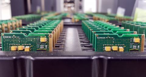
Broadly speaking, DFM analysis applies to anything that needs to be manufactured at scale. Manufactured products need to be designed to fit the process being used for high-volume production, so a design needs to be inspected to ensure nothing in the design will create low yield, defects, or low lifetime. These days, your PCB fabricator and PCB assembler might be on opposite sides of the globe, and it’s critical to ensure they all have access to a single, controlled store of project information to perform DFM analysis.
DFM analysis for PCBs involves checking whether the design will conform to your manufacturer’s processes for fabrication and assembly. Any experienced designer should know that the list of possible design choices that can compromise quality is long. I know that I still haven’t memorized every possible manufacturability problem that might lurk in a design, so I often rely on my fabricator to inspect my boards when I’m about to put in a fabrication run.
Inspect Your Design Often
This brings up an important point: when should you run some DFM checks on your design? If you’re doing some simpler boards, it’s probably fine to rely on your fabricator to run a final DFM check before production; repeated DFM deep-dives just take up excessive time when your fabricator can perform this quickly. For something more advanced, like high-layer count mixed-signal boards with tight clearances and multiple signaling standards, multiple DFM analysis runs are necessary to catch potential quality problems early.
The best way to prevent unnecessary design changes before manufacturing is to do DFM analysis at several different times:
- When selecting components: This mostly relates to passive component sizes, particularly 0201 and 01005. If you must use these small components, just make sure your manufacturer can handle these.
- During floorplanning: At this point, we’re still determining some basic aspects of the board like possible layer count, range of trace widths, via sizes, whether we’ll need to go to HDI, which PCB laminates to use, and which IPC Producibility Level will be applicable to the design.
- After component placement: Once you’ve placed components, consider the assembly process, particularly regarding soldering in double-sided SMD boards. Also think about how any grounded components will solder to their reference plane and whether they need thermal reliefs.
- While planning the stackup: You’d be surprised how many stackups need to be modified before a design can be put into fab. This one is as simple as asking your fabricator for a verified stackup table.
- After generating Gerbers: Some defects are easier to see in your Gerber files, so it’s best to scan your Gerbers for things like overlapping drill hits and via aspect ratios.
- In collaboration with the MCAD team: In some cases, placement of solderable connectors or other mechanical elements can create excessively tight clearances.
There are a few of these points that are worth elaborating on as they may not be often discussed in some other articles.
Component Clearances
Some points that apply to connectors will apply to any other component, but there is one other point around clearances that is worth checking. Make sure you have allowed for expansion during assembly, especially on connectors with a plastic shroud or base. If two components are too close and they expand during soldering, they can both lift off the board during assembly.

Looking at Footprints
Obviously, you should put in the effort to make sure your footprints are verified. This can be done manually, or by only using verified components direct from manufacturers when they are available. However, once a footprint goes into the layout, you’ll need to check solder mask openings, clearance to vias, clearance to other components, via aspect ratios, and more. If you’re not using software with the right rules-checking features, you might leave a thermal pad floating, or you might place a drill hit too close to a solder fillet. You can look at the PCB layout directly, but it’s perfectly fine to generate preliminary Gerbers and compare your layers (see below).

Stackup Check
It might sound simplistic, but you’ll pass this one with flying colors if you just ask your fabricator for a stackup with your desired layer count and layer arrangement. They’ve already done the DFM analysis needed to ensure specific layer stacks will pass through their process. They’ll give you the trace width, trace spacing (for differential pairs), and layer thickness you’ll need to use with your desired laminate materials. In some cases, you might be surprised to find that your desired laminate material is unavailable and you’ll need to use a close equivalent.

For 4-layer stackups, you’ll likely receive the standard 8mil/40mil/8mil S/P/P/S stackup giving 62 mil total thickness. More complex stackups may require a custom table, especially when you have a board that needs impedance controlled routing. If you get the stackup information early, you won’t risk applying the wrong trace and spacing needed for controlled impedance, everything will already be verified.
DFM Analysis Before Fabrication
Once you’ve finished your board and you’ve sent it in for fabrication, your manufacturer should run their own DFM analysis using your finalized Gerber files. Note that I write “should” here because not all manufacturers will do this; with some manufacturers, you upload your Gerbers and they will produce the board exactly as it appears in your fab files without question. For some manufacturers, you’ll need to request this level of service explicitly as different service levels will only be available as an add-on.
Once you get your DFM analysis from your manufacturer, you’ll see a lot of results in the following two areas: checks of clearances against process capabilities, and checks against specific industry requirements.
Checking Feature Sizes Against Process Capabilities
When you do put your design files in with your fabricator and they run their DFM analysis, you’ll probably see a lot of results around clearance checks. The fabricator should already check the areas listed above, but they’ll also need to compare your feature sizes and clearances against their process capabilities. Even if you went through this process with preliminary Gerbers as part of quoting, it’s best to just run this again as you may have missed something.
An example DFM analysis report from one of my preferred ITAR fabricators is shown below. In this table, we can see where spacing, annular ring sizes, and clearances between plated through-holes and copper. From the bottom row, you can see that my trace-to-copper clearance setting is too low, and the pads on some footprints have small annular ring sizes.

In this example, we have multiple errors along a particular footprint, which just happens to be a TO-92 package. In this case, the hole size in the built-in library was too large, which forced the annular ring around the edge to be too small in order to maintain clearances. After resizing the hole, we were able to make room for a Class 2 annular ring while still leaving plenty of clearance to prevent bridging.
For a large, complex design with thousands of nets, how does your fabricator check every possible feature in your PCB layout? There are applications that help automate this process and will compile a report with any process violations. Some manufacturers have their own applications they’ll use internally, while others will give you access to a downloadable program you can use to check your design before manufacturing.
IPC Class Compliance Review
Another area of design requirements that may take more experience is a review of compliance with IPC Classes. One important point to indicate during the quoting process is which level of IPC qualification you’re seeking, if any. This involves checking for teardrops, annular ring sizes, drill and pad diameters vs. copper weight, ability to plate vias and holes, and dielectric thickness requirements, just to name a few of the main reliability requirements. The physical layout will be compared against fabricator capabilities to ensure the resulting design can meet qualification and performance requirements defined in the IPC standards, and changes will need to be made prior to fabrication.
How to Get Your Design Data to Your Fabricator Quickly
What’s the fastest way to get files into the hands of your manufacturer, and how can you ensure they fully understand your design intent? You’ll need the best set of cloud collaboration tools you can find. These days, with everything being done digitally, PCB designers need tools to help them collaborate on complex projects and share them with their manufacturing partners. With the Altium 365 platform, it’s easy to quickly share everything from full project releases to individual design files with your manufacturer, other team members, and customers.
Altium 365 also helps streamline DFM analysis with a complete set of documentation features, including:
- Component and library hosting and management tools
- An integrated version control system based on Git
- Integration with internal database tools or external version control applications
- User access and management features
Inside Altium 365, there’s an extremely convenient way to get your board into your fabricator with the Send to Manufacturer feature. Once a project is released into your Altium 365 Workspace, you can go into your project release and click the “Send to Manufacturer” button at the top of the screen, as shown below. Your manufacturer can then open the project in Altium Designer, or they can download the release files and put your fabrication files through a DFM analysis application.

Once your design is with your fabricator, they can comment on specific points in the design, which will help ensure there is no confusion when reading a DFM analysis report. These comments can then be viewed online in Altium 365 through your browser, or in the PCB layout when you open your project in Altium Designer. No other cloud-based service helps you go through multiple rounds of DFM analysis like Altium 365.
The fastest way to get your design through multiple rounds of DFM analysis while tracking changes to projects throughout the process is to use the Altium 365™ platform. You’ll have all the tools you need to share, store, and manage all of your PCB design data in a secure cloud platform. Altium 365 is the only cloud collaboration platform specifically for PCB design and manufacturing, and all the features in Altium 365 integrate with the world-class design tools in Altium Designer®.
We have only scratched the surface of what is possible to do with Altium Designer on Altium 365. You can check the product page for a more in-depth feature description or one of the On-Demand Webinars.

About Author
Related Resources
Table of Contents
Design to Release, Without the Friction
- Keep reviews tied to the right version
- Reduce handoff confusion and rework
- Spot sourcing and release risk earlier
- Work solo, share when needed
Get Started
Thank you, you are now subscribed to updates.


