


The Essential Guide to Through-Hole Resistors


Resistors might seem like humble components, often overlooked in favor of more complex devices like microprocessors or sensors–however, these small yet mighty components play a critical role in ensuring that circuits function smoothly and efficiently. Whether you're designing a simple LED circuit or a complex computer system, resistors are fundamental in controlling voltage, protecting sensitive components, and managing current flow.
We'll explore the different types of through-hole resistors available, how they work, and their specific applications in various circuits. Whether you're revisiting the basics or expanding your knowledge, this article will be a valuable resource in your engineering toolkit.

How Resistors Work
Think of an electric circuit as a system of water pipes. The flow of electricity is akin to water moving through the pipes. Just as a narrower section of pipe would reduce the flow of water, a resistor restricts the flow of electric current.
Inside a resistor, the material—typically made of carbon, metal film, or wire—resists the movement of electrons. This resistance converts a portion of the electrical energy into heat, which dissipates into the surrounding environment. The amount of resistance is measured in ohms (Ω), with higher values indicating greater resistance and, thus, less current flowing through the circuit.
When a resistor is installed in a circuit, it drops the voltage across it (like the pressure drop in the narrower pipe), reducing the current to a level that other components in the circuit can handle. This makes resistors vital in setting the right conditions for operating LEDs, transistors, and other electronic components. By carefully choosing the appropriate resistor value, engineers can control the circuit's behavior, ensuring stability and efficiency.
In summary, a resistor acts as a gatekeeper in a circuit, allowing only a controlled amount of current to pass through, thus safeguarding the entire system and enabling it to function as intended.
Types of Through-Hole Resistors
Resistors come in various types, each fulfilling a specific function within an electronic circuit. Understanding these different types of resistors helps engineers and designers select the appropriate one for their application, ensuring optimal performance and reliability.
Fixed Resistors
Fixed resistors are the most common resistor type in electronic circuits. They're used in almost every electronic device, from controlling the current flow in LED circuits to setting the gain in amplifiers and stabilizing the biasing of transistors. As the name suggests, they have a fixed resistance value, meaning they cannot be adjusted once manufactured. They provide a specific amount of resistance, and their value is determined by the materials and construction used. Common types of fixed resistors include:
- Carbon Composition Resistors: Made from a mixture of carbon powder and a binding material, these resistors were widely used in early electronic circuits. They're known for their ability to withstand high-energy pulses but are less common today due to their higher noise levels and lower precision than modern alternatives.
- Metal Film Resistors: These resistors are constructed by depositing a thin metal layer onto an insulating substrate. Metal film resistors offer high accuracy, low noise, and excellent stability, making them ideal for precision applications in measurement and audio equipment.
- Wirewound Resistors: Created by winding a metal wire (usually nichrome) around a ceramic core, wirewound resistors can handle high power levels and are often used in applications requiring heat dissipation, such as power supplies and motor controls.

Variable Resistors
Also known as adjustable resistors, variable resistors enable manual adjustment of their resistance value. They're found in devices that require user input for adjustment, such as tuning a radio or adjusting the brightness of a display. They're also used in circuits where conditions change frequently, and resistance needs to be varied to maintain performance. These resistors are essential when a circuit needs to accommodate varying conditions or when fine-tuning is necessary. Types of variable resistors include:
- Potentiometers: Potentiometers are the most well-known type of variable resistor. They feature a three-terminal design with a rotating or sliding contact (wiper) that adjusts the resistance between two terminals. Potentiometers are commonly used as volume controls in audio equipment, where the user can adjust the resistance to control the output level.
- Rheostats: Similar to potentiometers, rheostats are designed for higher current applications. Unlike potentiometers, rheostats typically use only two terminals and are employed to adjust the current flowing through a circuit. They are often found in light dimmers and motor speed controls.
Specialty Resistors
Specialty resistors meet specific needs in advanced or demanding applications. They're used in applications requiring precise resistance control in response to environmental changes like temperature regulation, surge protection, and compact electronic devices where space is limited. Types of specialty resistors include:
- Thermistors: Thermistors are temperature-sensitive resistors whose resistance changes significantly with temperature. There are two types: Negative Temperature Coefficient (NTC) thermistors, which decrease in resistance as temperature rises, and Positive Temperature Coefficient (PTC) thermistors, which increase in resistance with rising temperature. NTC thermistors are commonly used in temperature sensing and circuit protection, while PTC thermistors are used in overcurrent protection and self-regulating heating elements.
- Varistors: Varistors are voltage-dependent resistors that change resistance in response to voltage levels. They are primarily used for surge protection in circuits, as they can absorb and dissipate energy spikes, protecting sensitive components from damage.
Common Through-Hole Resistor Values and Color Coding
Resistors are available in a wide range of values. Understanding how these values are determined and represented is crucial for selecting the right resistor for any electronic circuit.
Resistor Values
Resistor values are measured in ohms (Ω), with higher values indicating greater resistance. Standard resistor values follow a series of preferred numbers based on logarithmic sequences, such as the E6, E12, and E24 series. These series represent common resistor values spaced logarithmically across a decade (a range between 10 and 100 ohms, for example). Here are some standard series examples:
- E6 Series: Includes values like 10Ω, 15Ω, 22Ω, 33Ω, 47Ω, and 68Ω. It's often used where precision is not critical.
- E12 Series: Adds more intermediate values, including 12Ω, 18Ω, 27Ω, 39Ω, 56Ω, and 82Ω. It's commonly used in many general-purpose applications.
- E24 Series: Provides even finer granularity, including values like 11Ω, 13Ω, 16Ω, 20Ω, 25Ω, and so on. This series is used when precise resistance values are required.
The selection of a resistor value depends on the requirements of the circuit, including the desired current flow, voltage drop, and the role the resistor plays (e.g., limiting current, dividing voltage, and biasing transistors). For example, in an LED circuit, the resistor value is chosen to ensure the LED receives the correct current, preventing it from burning out.
Through-Hole Resistor Color Code
Resistor values are often indicated using a color code, especially in through-hole resistors. This color code is a series of colored bands painted on the resistor body, where each color corresponds to a number. The code typically consists of four to six bands:
- First Band: Represents the first significant digit of the resistor value.
- Second Band: Represents the second significant digit.
- Third Band (if present): Represents the third significant digit (used in 5-band resistors).
- Multiplier Band: Represents the power of ten by which the significant digits should be multiplied.
- Tolerance Band: Indicates the tolerance, or precision, of the resistor (e.g., ±5%, ±1%).
- Temperature Coefficient Band:
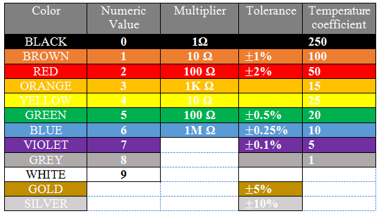
Color code for 4, 5, and 6 band through-hole resistors.
Resistors in Series and Parallel
Understanding how resistors behave when connected in series or parallel is essential for designing circuits that meet specific electrical requirements. Each configuration has distinct effects on the circuit's overall resistance and current flow.
Series Configuration
When resistors are arranged in series, they're connected end-to-end, so the same current moves through each resistor. The total or equivalent resistance of the circuit is the sum of the individual resistances. The key characteristics of series configuration are:
- Total Resistance (R_total): The overall resistance is simply the sum of all resistors in the series. Mathematically, this is expressed as:
Rtotal=R1+R2+R3+⋯+Rn
For instance, if you have three resistors with values of 10Ω, 20Ω, and 30Ω connected in series, the total resistance would be 60Ω. - Current Flow: The same current moves through each resistor in the series. However, the voltage across each resistor is different and proportional to its resistance.
- Voltage Drop: The total voltage drop across the series resistors equals the sum of the voltage drops across each resistor. This characteristic is helpful in applications where voltage needs to be divided among components.
Series resistors are commonly used in voltage divider circuits, where a specific fraction of the input voltage is needed to power different parts of a circuit. For instance, in a battery-powered LED flashlight, resistors in series can help reduce the voltage to match the LED's requirements.
Parallel Configuration
In a parallel configuration, resistors are connected across the same two points, so each resistor has the same voltage across it, but the current divides among the resistors. The total (or equivalent) resistance in a parallel circuit is always less than the smallest individual resistor. The characteristics of parallel configuration are:
- Total Resistance (R_total): The overall resistance is determined by taking the reciprocal of the sum of the reciprocals of each resistor. Mathematically:
Rtotal1=R11+R21+R31+⋯+Rn1
For example, if you have three resistors with values of 10Ω, 20Ω, and 30Ω connected in parallel, the total resistance would be approximately 5.45Ω. - Current Distribution: The current flowing through each resistor in parallel is different and inversely proportional to its resistance, meaning resistors with lower resistance will carry more current.
- Voltage Consistency: The voltage across each resistor in a parallel configuration is the same and equal to the source voltage.
- Practical Example: Parallel resistors are often used in power distribution networks where multiple components need the same voltage but may draw different amounts of current. In home wiring, parallel circuits ensure that appliances and lights receive the same voltage regardless of how many devices are turned on.
Practical Examples in Electronic Devices
Understanding how to use resistors in series and parallel configurations allows engineers to design circuits that distribute voltage and current most effectively, ensuring reliability and performance across several electronic devices. Here are some examples of series and parallel configurations in devices:
- String Lights: In older holiday string lights, resistors (or light bulbs) are connected in series. If one bulb burns out, it creates an open circuit, causing all the lights to go out. This is a simple example of a series circuit where the current must pass through each light bulb in sequence.
- Voltage Dividers: As mentioned, series resistors are essential in creating voltage dividers, commonly used in sensor circuits to produce a voltage corresponding to physical measurements like temperature or light levels.
- Power Supply Circuits: In power supplies, parallel resistors ensure that each component receives the correct voltage, regardless of the power drawn by other components. This is crucial in complex circuits like those in computers, where different components require different amounts of current.
- LED Arrays: In modern LED lighting systems, LEDs are often connected in parallel to ensure that each LED receives the same voltage and operates consistently, even if individual LEDs draw different amounts of current.
FAQs About Resistors
Below, we've answered some common questions about resistors.
What does a resistor do?
A resistor limits the flow of electric current in a circuit.
What is a resistor in a circuit?
A resistor is a component that controls current and voltage levels in a circuit.
How do resistors work?
Resistors work by providing resistance to the flow of electric current, converting some of the electrical energy into heat.
What does a through-hole resistor look like?
A resistor typically looks like a small cylindrical component with colored bands or a flat chip (in surface-mount versions).

Surface-Mount Device (SMD) Resistors
SMD resistors are tiny resistors designed for surface-mount technology, allowing them to be placed directly on the surface of a PCB without the need to use through-holes for mounting and soldering. These resistors are the standard components used in commercial products due to their small size and the fact that they do not use any real estate on inner layers. Most commercial products do not make use through-hole resistors due to their large size unless the circuit in question will need to handle high power.
We'll look at SMD resistors in more detail in an upcoming article.

Compare Resistors & Find the Best One for Your Project
With Octopart's powerful search engine, you can easily explore millions of electronic components, compare specifications, and source the exact resistors you need—all in one place. Start your search on Octopart today and ensure you're getting the best passive components and other electronic parts for the job.
About Author
Related Resources
Related Technical Documentation
Table of Contents
- How Resistors Work
- Types of Through-Hole Resistors
- Fixed Resistors
- Variable Resistors
- Specialty Resistors
- Common Through-Hole Resistor Values and Color Coding
- Resistor Values
- Through-Hole Resistor Color Code
- Resistors in Series and Parallel
- Series Configuration
- Parallel Configuration
- Practical Examples in Electronic Devices
- FAQs About Resistors
- What does a resistor do?
- What is a resistor in a circuit?
- How do resistors work?
- What does a through-hole resistor look like?
- Surface-Mount Device (SMD) Resistors
- Compare Resistors & Find the Best One for Your Project
Design to Release, Without the Friction
- Keep reviews tied to the right version
- Reduce handoff confusion and rework
- Spot sourcing and release risk earlier
- Work solo, share when needed
Get Started
Thank you, you are now subscribed to updates.