LED Driver Selection for High Power Lighting
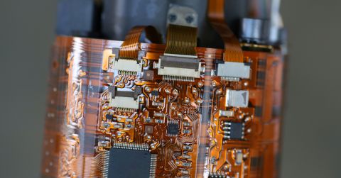
 This high power LED panel needs an LED driver circuit to provide stable power output.
I always remember playing with LEDs and driving them with a breadboard power supply or a battery. With small LEDs driven at low voltage/current, you can drive them with any power source. For high power LEDs, including white LEDs, your lighting system needs to have more sophisticated regulation to ensure stable current and voltage are dropped across each LED in the system.
While you could manually build a regulator with feedback from several components, it’s much easier to use an LED driver to control your system. These components are specifically designed to source DC power for LEDs with high efficiency. Here are some tips for selecting LED drivers for your next high power lighting system and some example components you’ll find on the market.
Why Use an LED Driver?
Think of an LED driver as an integrated power regulator specifically designed to source constant voltage (current) with adjustable current (voltage). For high power lighting systems, you can integrate an LED driver to control the LED power output as part of your regulation strategy. The upstream regulator stages convert a high input voltage (typically AC mains or high DC voltage) down to a lower DC level.
By adjusting the power output from the LED driver, you can adjust the brightness of your LEDs. High power LED drivers are usually available as surface mount components with an exposed pad for heat dissipation into your substrate. For dimming control, some LED drivers are internally programmable with an I/O port, while others use PWM dimming on a MOSFET driver to control power output (similar to a switching regulator).
PWM Dimming
A popular method for adjusting the brightness in a strand of LEDs is to use a PWM signal. The diagram below shows how to use an MCU for PWM dimming. In this example, the 50 kOhm resistor on the output MOSFET creates a feedback loop to provide high voltage/current output for the downstream LEDs. Note that, in this arrangement, we’re looking at white LEDs in parallel, although series implementation is common. Using an MCU allows the user to control the power output by adjusting the PWM duty cycle. This can be done based on a sensor reading (e.g., a temperature sensor) or using some input from the user.
 Example driving of parallel LED strands with a PWM signal from an MCU.
In this example, the LED driver acts like a parallel current regulator, while the PWM signal and the MOSFET drive the LEDs on and off near the forward voltage at the switching frequency. The average power is then linearly proportional to the duty cycle for the PWM signal. You can also add a high power current-limiting resistor on each leg (some LED modules will have this included) to prevent over-driving during switching.
The example above is very useful as the designer can program multiple power settings into the MCU. You also don’t need an expensive MCU for this application. I recently used a simple 8-bit ATTiny MCU and stored multiple PWM settings into the EEPROM, which could be toggled by the user with a push button.
Once you’ve decided how best to regulate the output power and provide dimming (if desired), it’s time to choose a driver that will source the power your lighting system needs.
Tips for Choosing LED Drivers
LED drivers have a range of topologies that mimic standard power regulators, but they may include other functions like programmability, current-sense feedback for regulation, and temperature sensing. For high power LED drivers, here are the important specifications to consider.
-
Output voltage and current. In order to get the LED to turn on, the output power needs to be at or above the diode’s forward voltage and forward current. Some LED drivers will act like buck or boost converters that output at or above the forward DC voltage with specific current, thereby providing the desired power output.
-
Series vs parallel output. Smaller LED drivers may only have a single output at high voltage and fixed current, which allows a strand of LEDs to be driven in series. LED drivers with multiple outputs (see above) are generally intended for parallel use.
-
Integrated vs. external PWM. Some LED drivers will include a PWM generator and will source the signal to a MOSFET directly.
-
Power efficiency. For high power systems, this is an important point as it determines how much power is lost as heat.
Regarding the second point above, you could always output to multiple LED strands in parallel, where each strand contains multiple LED strands in series. Pay attention to the total forward voltage and current that is output as this will determine how many series/parallel strands you can use in your lighting system.
Here are some example LED drivers you can use in your high power lighting system.
NXP Semiconductors, SSL5015TE
The SSL5015TE LED driver from NXP Semiconductors is one of the newest high voltage/low current LED drivers on the market for lighting systems requiring connection to rectified AC mains. This component includes an internal regulator and JFET for high voltage output up to 300 V and 2 A. It also includes a pin for an NTC thermistor for thermal protection, or this pin can be used with an external PWM signal to toggle the output current and provide dimming. Because the output voltage is so high, it is best to use this driver for a strand of LEDs that require low forward current in series. The application diagram below shows a typical LED driver circuit involving this component.
 Example application diagram, from the SSL5015TE datasheet.
Diodes Inc., AL8843QSP
The AL8843QSP LED driver from Diodes Inc. is a DC-DC buck-mode LED driver rated for automotive lighting. This component can accept input ranging from 4.5 to 40 V and outputs at up to 3 A (97% efficiency) with an integrated MOSFET. Dimming can be controlled with an external DC signal or a PWM signal (up to 1 MHz) on the CTRL pin. This component also includes short circuit protection for high power LEDs.
 Application circuit for series LEDs, from the AL8843QSP datasheet.
Analog Devices, LT3744
The LT3744 LED driver from Analog Devices (Linear Technology) provides moderate voltage (36 V) and high current output (20 A DC, 40 A pulsed). These output levels make this component one option for mixed series/parallel strands of high power LEDs. Dimming is controlled through a combination of 3 external PWM signals, which is then fed to an external high power MOSFET. It also accepts a wide input voltage range (3.3 V to 36 V), making it flexible for small and large lighting systems.
 LED driver application circuit for a projector with graph showing PWM dimming control, from the LT3744 datasheet.
Whether you’re designing a high power lighting system, you need to select LED drivers, FETs, and passives that ensure stable power output and safety. When you’re looking for components for your next high power lighting system, try using the component search and filters from Octopart.
Stay up-to-date with our latest articles by signing up for our newsletter.


