


Letting Your Boards Sort Themselves Out

At a Glance
Let identical PCBs self-configure at startup. No DIP switches or resistor stuffing needed. Discover how embedded devices assign roles with code.


Architecting for identical PCBs in a larger system requires coordination both on the board design side and with the software engineers to ensure that each board is treated uniquely. A very common approach is to stuff resistors on unique footprints during pick and place, so each board has its own configuration. DIP switches are also a popular option. Most of these options, however, require physical intervention with your boards. This means that if you need to change your "unique identifier,” something physical must also undergo change.
In this article, we will explore the idea of self-configuration between identical embedded devices. These devices will be completely identical from both a hardware and software perspective, but acquire their “uniqueness” upon startup using a lightweight coordination protocol.
Overview
The simplest, easiest way to demonstrate this software-based solution would be through the use of Arduinos, which are super easy to set up, program, and prototype with. It’s not a coincidence that a lot of my tutorials consist of Arduinos for basic prototyping concepts. When writing basic software algorithms, it’s even better if we can simply test this on our local PC first. This is exactly what is done in the project repository. Before we dive into the code, let’s discuss some of the high level concepts.
In Figure 1, we demonstrate an example sequence of how each node gets configured upon startup. Since we’re powering on devices sequentially, the process is straightforward. The first node will start up and announce that it is “here” on the shared bus (using the “HELLO” message command - which is represented as a number). No one responds within the timeframe specified so it will assume the role of coordinator. Just to be safe, it will announce on the bus that it is claiming the coordinator role (via the “CLAIM” message). The next device comes along and wants to join the network. It announces its existence, and the coordinator immediately responds to let it know that there is a coordinator. The second device requests to JOIN the network, and then the coordinator will ASSIGN it an ID. The next device will perform the same routine, and this can go on forever.
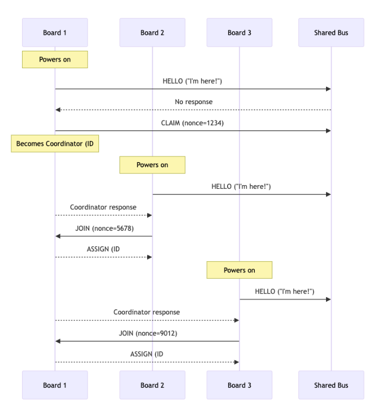
In the event that two devices attempt to become the coordinator upon startup, we use a nonce (random number used once) as the tie breaker. Whoever’s nonce is the highest becomes the coordinator. Think of this as a real time “rock, paper, scissors.”
Simulate Before Prototyping
In the above design, you will notice that there is a good portion of this project that is algorithmic, meaning parts of it don’t require hardware at all. A common mistake engineers will make is to start the development process directly on the device itself. Just from the perspective of programming the device every time, we lose lots of precious time waiting for that compile and flash process to take place. Of course when we need to test hardware peripherals, we must always test on target, but there is a lot we can do on our PC prior to running the code on target.
In the project repository, you will notice a folder under the path “shared/core.” The files contained within the folder are the core functionality of the project and common across all devices (regardless of their architecture). In this example, we run the simulation locally and on Arduinos, but the code can be shared across various types of devices and architectures (assuming they run C code). This is a foundational concept in embedded system design and often overlooked. While we won’t go into painstaking detail of the code itself (see “shared/README.md”), there are some high level concepts that are important to highlight:
- The files in “shared/core” require no preprocessor conditionals such as #ifdef statements. Preprocessor conditionals muddy up your code and make it hard to follow (at least that’s my opinion).
- Anything that requires an abstraction to a hardware layer lives in Hardware Abstraction Interfaces (HAL) that keep universal functions, such as print() operations, generic and easy to use across devices and platforms.
- The abstraction between the algorithm and the hardware/simulation calls enable multiple people to work on different parts of the project without ever interfering with each other. While modern Source Code Management systems, such as Git, help a lot with integrating people’s work in parallel, it’s always ideal to try and segregate out work amongst files if possible.
Proof of Concepts with Arduinos
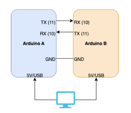
When possible, I always like to prototype concepts with simple, easy to use boards, such as the Arduinos. Since this project requires multiple microcontrollers, I can just use two Arduinos as a baseline to test it out. The hookup is quite simple. Just cross over the Tx/Rx lines and connect the grounds together as well. If you’re using the same computer to control Arduinos, technically the USB cable acts as the shared ground, but it’s better to just directly connect the grounds together.
Note that if you’re going to use different types of Arduinos (e.g. Arduino Uno with an Arduino Uno R4), you will need to use different serial ports. Consult “docs/DIAGRAMS.md” for the wiring diagrams. At this point, you’ll need to compile and upload the Arduino sketches. There are a few different ways to do this, but to keep things simple we’re going to use the manual, old-fashioned way (also captured under “docs/ARDUINO_IDE_SETUP.md” in the project repository). Given the drawbacks of the Arduino IDE, the ideal scenario is if you can have two machines, each running an Arduino separately. This can be as simple as a laptop + PC or PC + Raspberry Pi, etc. Once you have the Arduino IDE up and running, open up “arduino/AutoSort/AutoSort.ino” and hit upload (after ensuring your Arduino is set up and ready to go). Do the same on your other machine as well. You’ll also want to synchronize this so that the Coordinator comes up first, and then the next node will be programmed/plugged in afterwards. This is what you should see from the Coordinator side first:
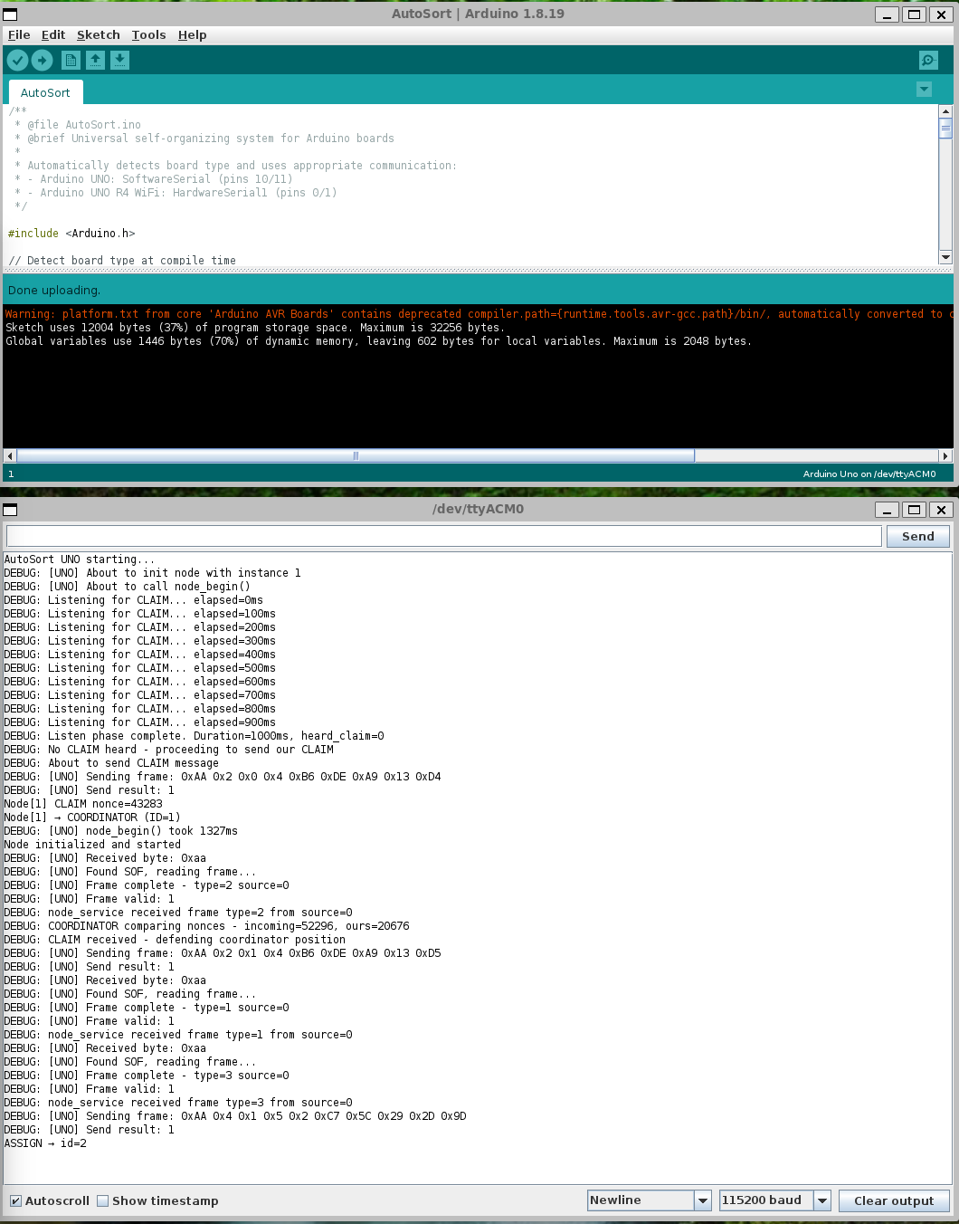
And the joining node will look like this:
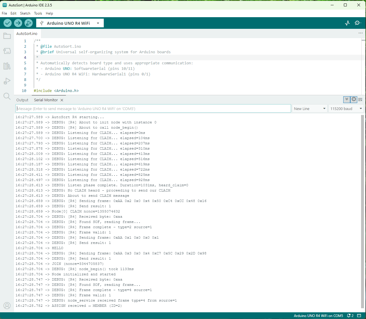
As you can see from the logs, the second node attempts to claim the coordinator role, but the first node won’t have it. The first node defends its position, and then the second device acquiesces by joining the network. The Coordinator then provides the device with a node ID and everyone is happy.
Conclusion
Leaving the coordination and orchestration of node networks to software only eliminates the need for custom pick and place instructions and code that goes along with it. By following the system (or similar system) discussed in this article, you can design, build, and ship identical devices that will all become unique on their own. Of course, this approach isn’t going to be a one-size-fits-all. Safety-critical systems such as aerospace, military, and medical applications all require 100% predictability and accountability for every single device on a network. Some systems may want a methodology where they can track locations of PCBs using customized IDs (i.e. via DIP switches or resistor stuffing). For those cases this may not be the solution, but for all others this is definitely worth exploring.
Want to try it? Check out the GitHub repo and experiment with your own boards.
About Author
Related Resources
Related Technical Documentation
Table of Contents
Design to Release, Without the Friction
- Keep reviews tied to the right version
- Reduce handoff confusion and rework
- Spot sourcing and release risk earlier
- Work solo, share when needed
Get Started
Thank you, you are now subscribed to updates.