


Shrinking Arduino Projects: Atmega328P and Nothing More

At a Glance
Learn how to shrink Arduino projects by going straight to the Atmega328P chip. Simple steps to faster, cleaner prototyping.


I’ve been prototyping and playing around with Arduinos since the first Arduino Uno came out. I was just starting college and I fell in love with the device from day one. Fast-forward a few years later, and I needed to rapidly put together a prototype for my senior design project. To move fast, the Arduino was the only platform out there at the time that came with lots of modules/shields, libraries out of the box, and a simple IDE to pull a prototype together in no time. Almost 20 years later, the Arduino is still a slam dunk, providing a vast array of modern shields, libraries, and even better IDE to work with.
In this article, we’re going to explore something that people could have done almost 15 years ago but not done enough: dropping the Arduino and developing with the Atmega328P chip directly. There are a myriad of reasons why people wouldn’t want to ditch their old Arduino, including the introduction of the Arduino Nano but taking a prototype to production typically requires dropping the printed circuit board (PCB) and going straight with the microcontroller unit (MCU).
What You’ll Need
A major challenge hardware engineers face with introducing MCUs is that they now have to learn embedded software. Arduinos, as stated in the introduction, have made this much easier. In order to stick with the Arduino ecosystem, there’s a natural tendency to slap some female headers on a PCB and drop an Arduino Nano on it. While this is certainly an option, after going through this tutorial, you will quickly realize that this is unnecessary in order to fully utilize the complete Arduino environment. I like to use the original Atmega328P that came with the Arduino Uno, because it’s tough and can be dropped onto a breadboard so easily. While the footprint is definitely bigger, I find it easier to work with, especially for entry level engineers. You can also drop it on a socket (just like the Arduino Uno) in case it blows, or you don’t want JTAG exposed on your PCB.
You can start prototyping with the Atmega328P right away, just using a breadboard, a power source, and a JTAG programmer (such as the Atmel-ICE). A decoupling capacitor between VDD and GND is a good idea, but not required to get started. In this repository, I demonstrate how to create a basic serial read/write sketch and load it directly on the Atmega328P chip using the Atmel-ICE programmer. There are quite a few programmers out there supported by the Arduino CLI tool (see the repository requirements for details on that) so you can shop around to see what works best for you. There are two, very important, caveats that come with using the Arduino environment in conjunction with the Atmega328P directly:
- You must burn the bootloader onto the chip and inform it to use the onboard 8 MHz oscillator. The Arduino defaults to using an external 16 MHz oscillator. If you don’t set this, then your sketches won’t run. This is called out in the README of the project.
- Since the Arduino is now using the 8 MHz internal clock (versus the external oscillator), we need to inform the tool of this change. You’ll see this called out at the top of the sketch file in that project: #define F_CPU 8000000UL.
That’s it. That’s all you really need to get started. The pinouts between an Arduino Uno and the Atmega328P are not exactly one to one so you’ll have to be cognizant of that as well.
Sample Project
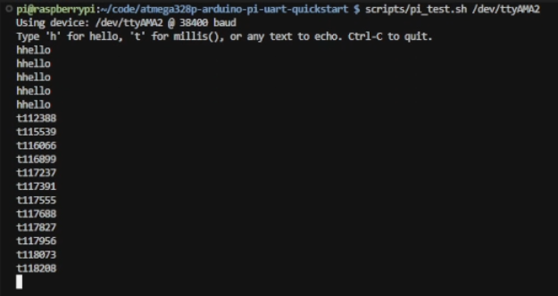
As you’re exploring the project repository, you’ll discover a script that automatically programs the device. This file significantly reduces the steps needed to get you up and running. Keep in mind that this works on a Linux based system (such as a Raspberry Pi) so it’s best to baseline on a device that supports Linux. It first grabs the package needed to program the Atmega328P directly (MiniCore), proceeds to flash the device with the bootloader settings, and then the compiled sketch. Keep in mind that you will need to follow the wiring instructions in the README to connect the Atmel-ICE (or equivalent) to the Atmega328P chip. You’ll also need a device that can communicate over UART to the Atmega328P for debugging (such as a Raspberry Pi, another Arduino, or a UART to USB cable). Once you upload the sketch, you can run the test and interact with the device over serial to see it echo “hello” and the free running time counter.
From Single Chip to Self-Organizing MCUs
At this point, we’re ready to tackle a more complex project. Let’s revisit the Self-Organizing MCUs Example that was featured in Letting Your Boards Sort Themselves Out. Rather than use full-on Arduinos in that example, I’ve decided I wanted to pair down the project to just two, point-to-point, Atmega328P chips on a breadboard.
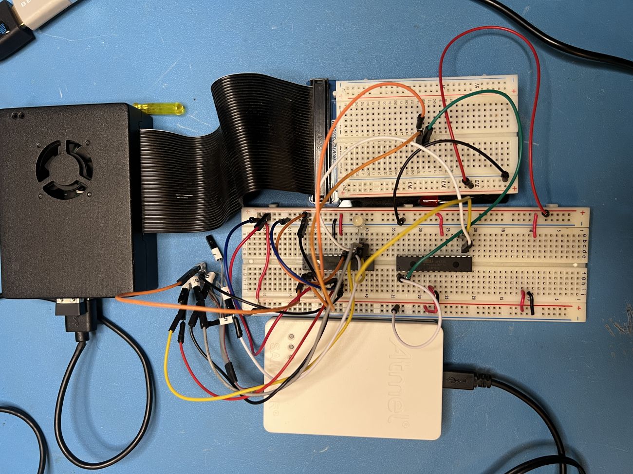
While the setup looks complex, the wiring you see in the image is mostly to support the JTAG setup and power/ground connections to the chips. The full wiring diagram setup can be found in the repository so you will need to follow that step there. For reference, this is what the wiring diagram should look like hooking up two Atmega32P chips with a Raspberry PI (for UART communication and power):
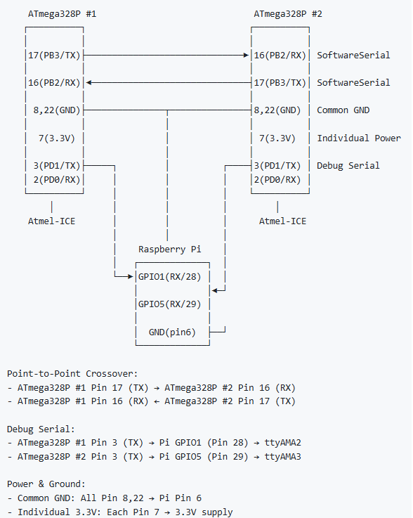
Note that this wiring diagram does not contain the hookups to the JTAG programmer. That should have already existed from the previous project. I can now take the Self-Organizing MCU project and run it on a breadboard with just the Atmega328P chips - no Arduino boards necessary. Running the make commands to build the project (make arduino-atmega328p) and program the device (make program-atmega328p), you should be able to get your project up and running pretty quickly. To program the second Atmega328P chip, I recommend swapping out the first chip with the second one and keeping all the existing wires in place.
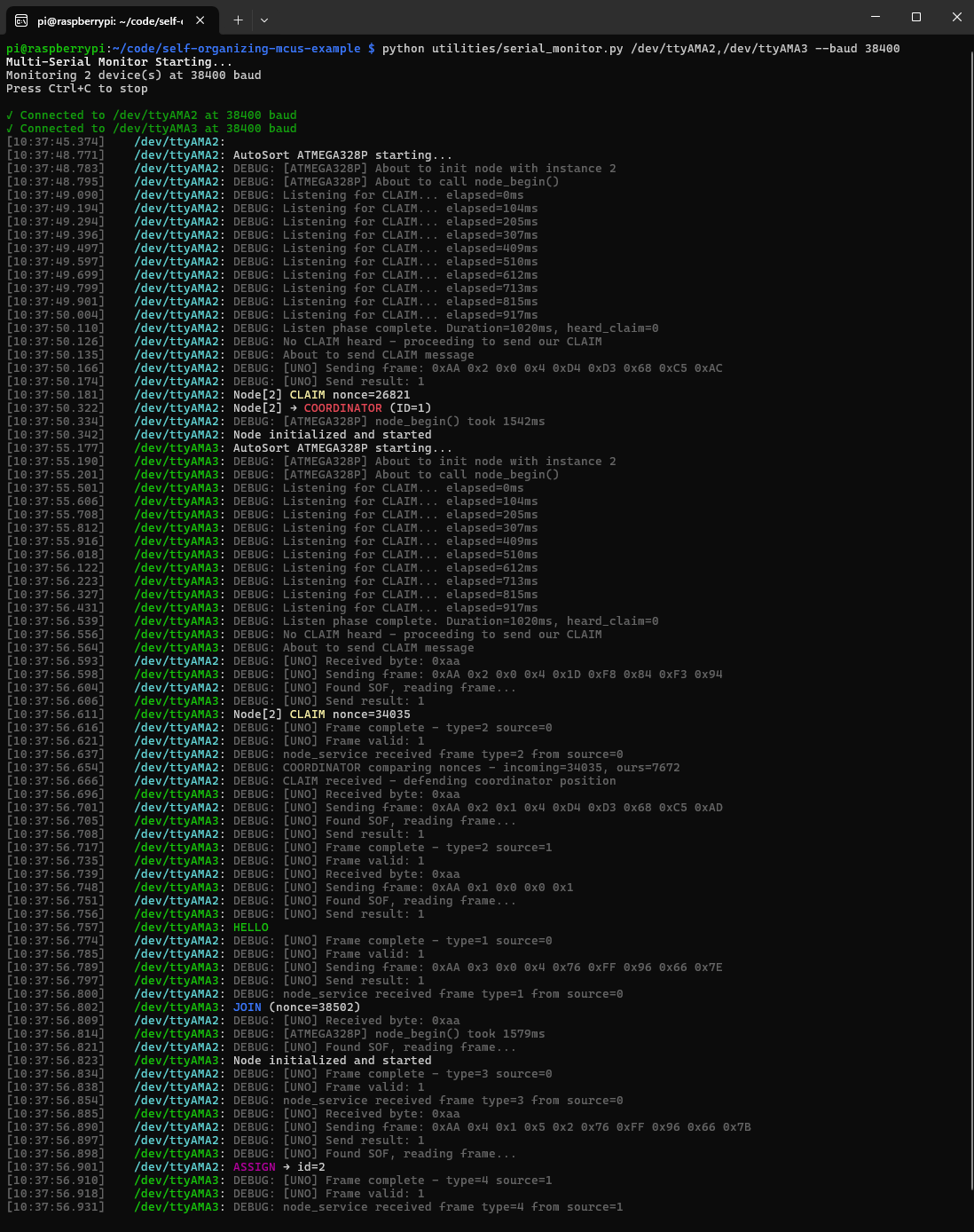
To run the example, first put both Atmega328P chips in reset by connecting pin 1 to ground (after programming them). Navigate to your terminal on Raspberry Pi and run the serial monitor script. From the root of the repository, the command would be:
python3 utilities/serial_monitor.py /dev/ttyAMA2,/dev/ttyAMA3
Now take the first Atmega328P out of reset (setting pin 1 to VDD) and observe the printout from the serial monitor application. After the printout completes, do the same with the second chip. You should see the first chip becoming a coordinator and the second one getting an ID assigned to it.
Conclusion
With these examples, we can start to see how powerful of an ecosystem we get to leverage with such a cheap, small chip. We can easily design these chips into large PCB projects and eliminate the need for complex software environments (or seasoned build/software engineers) that are needed when designing in bare MCUs.
Additionally, no external circuitry is needed either so we can drop these chips on board with sockets and nothing more. The most exciting part is that if you can play around with an Arduino, you can certainly do this just with a few extra steps. The major takeaway here is this: don’t be afraid to strip things down. Once you’ve followed this tutorial to completion, you’ll probably never want to go back.
About Author
Related Resources
Related Technical Documentation
Table of Contents
Design to Release, Without the Friction
- Keep reviews tied to the right version
- Reduce handoff confusion and rework
- Spot sourcing and release risk earlier
- Work solo, share when needed
Get Started
Thank you, you are now subscribed to updates.