


Tips to Reduce Bill of Material Cost


Introduction
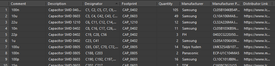
The bill of material, or BoM for short, is a key document for any hardware design project. In essence, it lists all components that are required to build a completed printed circuit board (PCB) assembly. The BoM lists additional information per component, such as component name or value, reference designator on the PCB, manufacturer, manufacturer part number, distributor link – just to name a few. An extract of a typical BoM is shown below, using Altium Designer’s Bill of Materials reporting tool.
Figure 1 Minimal BoM Example
A BoM, typically exported as an Excel spreadsheet or CSV file, is combined with other manufacturing information (for example, Gerber, pick ‘n’ place, and assembly information) and sent to a PCB manufacturer and assembly house to have the design produced.
Creating a BoM seems like a fairly trivial process – effectively, it is just a matter of using your ECAD tool’s BoM function to export a structured list of whatever components you have on your schematic and PCB. However, there are many ways we can improve our BoM, reduce its cost, and thus reduce the overall cost of having our design produced. This becomes more and more important as our production volumes increase.
Reducing BoM cost should be thought about right from the start of a new hardware design project, but we can still, in many cases, effectively reduce the BoM cost even close to the manufacturing step.
When attempting to reduce BoM cost, there are several aspects we need to consider. For instance, the actual cost of the parts themselves, procurement costs, and assembly costs. This article will outline some ways you can reduce your BoM cost – let’s get started!
Tip #1 – BoM Consolidation
BoM consolidation, as the name suggests, is a strategy to reduce the number of unique items in and thus the overall length of the BoM, by adjusting and combining similar items. Having a shorter BoM makes the procurement process easier, reduces the assembly effort and cost, and reduces inventory size – to name a few examples.
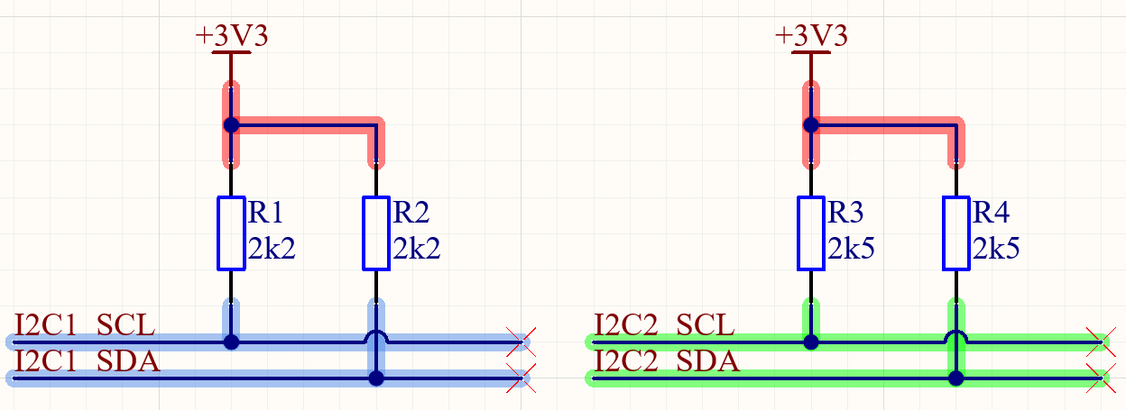
An example of BoM consolidation would be if we have several I2C interfaces in our design, but they are using different resistor pull-up values. If current consumption and speed requirements allow, we could use the same (for example, lowest of the values) pull-up resistors across all buses and thus reduce the BoM length.
Figure 2 Before BoM Consolidation
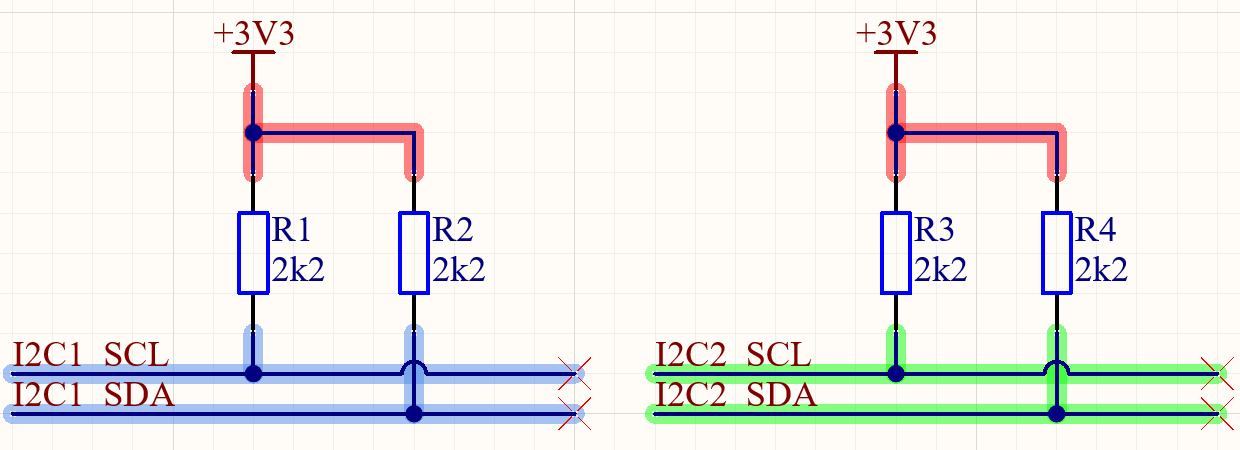
Figure 3 After BoM Consolidation
BoM consolidation could also happen by removing redundant sections or features of the design that were found to not be needed any more after testing.
Another cost factor that is not reflected above is the yearly production volume of 2.2k resistors vs. 2.5k resistors. Just as an example, compare these search results for 2.2k resistors versus these results for 2.5k resistors. The price difference is huge because 2.2k resistors are manufactured in much higher volumes and are therefore much less expensive than 2.5k resistors. A simple change like this leads to significant savings at high volume.
Tip #2 – Part Selection and Substitutes
A big part of reducing BoM cost can be of course to simply choose cheaper components, or components that are more commonly available. For instance, we may ask: do we really need 1% tolerance resistors for an I2C pull-up or is 5% or worse tolerance okay? The answer is most likely the latter and may drive down the BoM cost.
Similarly, for certain capacitors in our design, we may not need extended temperature range dielectrics, such as X7R and could go with slightly cheaper X5R equivalents. There are many examples of other parameters where similar thoughts can apply.
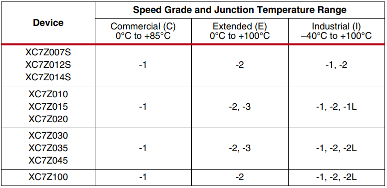
The same could be said for commercial vs industrial temperature grade parts, or the speed grade of the part. Typically, if the design and operating environment allows of course, it may be more cost effective to go with the less-expensive commercial temperature grade part.
Figure 4 Zynq Temperature and Speed Grades (Source: AMD)
Tip #3 – Packaging and Assembly Requirements
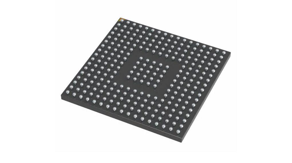
Component packaging and package sizes can have a significant impact on cost. For instance, an IC in a fine-pitch BGA-type package will be more costly to create a PCB for, assemble, and requires additional inspection steps (such as X-ray inspection), compared to a QFP-type package with exposed pins. This may also lead to a lower overall yield from the manufacturer.
Figure 5 BGA Package (Source: Distrelec)
Assembling these types of components on both sides of the PCB can also add assembly processing and inspection steps. Additional passes through reflow require additional machine time, which then adds to costs. However, if you use an alternative package, you can eliminate this additional cost. Unfortunately, not all engineering or feature requirements can be reached with lower-cost packaging, and this is something that has to be weighed when selecting parts.
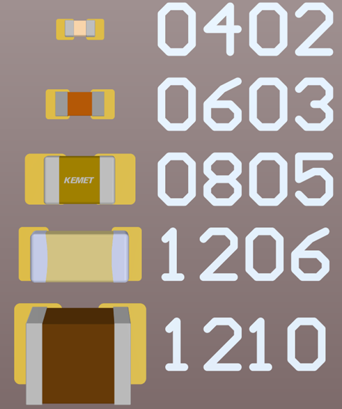
Similarly using 0201 vs 0402 (both imperial) may be a cost adder for certain assembly houses and may require more of the same parts to be procured due to losses during the assembly process.
Figure 6 Capacitor Size Comparison (Imperial)
As usual, the design constraints (size, being one reason) may not allow for this, but it is an option to keep in mind. It is important to speak to your PCB assembly house, to confirm if certain package types may be a cost adder.
Tip #4 – Inventory and Suppliers
Aiming to reduce the number of unique or different components across products can help streamline and simplify several process. For instance, the inventory management, storage, and supply chain effort may be reduced – again resulting in a reduced overall BoM cost.
Make sure also to keep your supplier options open and not rely on parts (unless absolutely necessary) that can only be acquired via a single source. Unexpected costs may arise due to suddenly depleted stock levels and elevated lead times.
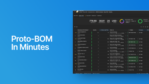
Octopart can help you figure out which various suppliers are available for the parts required in your design. Once buying volumes become very large, you will see significant reductions in cost by bypassing distributors and buying directly from the component manufacturer.
Tip #5 – PCB
The PCB itself is an additional item on a project’s BoM. If possible, reducing the manufacturing complexity of the PCB itself can thus reduce the overall BoM cost. For instance, a reduced layer count, cheaper surface finish, or cheaper materials – just to name a few examples – could be ways of increasing PCB yield and driving down cost. This of course depends on design constraints as usual.
Outro
We have explored a few ways of reducing the cost of a BoM in an electronics design. The ability to reduce BoM cost is critical in modern, high-volume products and a key part in many projects. Keep in mind however, that some methods are not applicable to some products, as their overall complexity and specificity is too high to allow for much variation in the BoM.

About Author
Related Resources
Related Technical Documentation
Table of Contents
Design to Release, Without the Friction
- Keep reviews tied to the right version
- Reduce handoff confusion and rework
- Spot sourcing and release risk earlier
- Work solo, share when needed
Get Started
Thank you, you are now subscribed to updates.