Wiring the Future: The Shift to Unified Electromechanical Design

At a Glance
Adopt unified electromechanical design. Sync ECAD-MCAD, route harnesses in 3D, and cut re-spins with bidirectional data and precise BOMs for reliable builds.


As global industries move toward highly integrated, mission-critical systems, the complexity of internal electronics has grown exponentially. From life-saving medical devices to advanced aerospace systems, the primary challenge in modern electronics product development is no longer just the design of the Printed Circuit Board (PCB), but the management of the intricate web of wiring and harnesses that connect these systems. This article examines the shift from hardware-centric to systems-level design and argues that accurate, bi-directional CAD data transfer between electrical and mechanical domains is a requirement for operational reliability and market viability.
Key Takeaways
- Modern systems have shifted from simple PCB‑focused designs to dense, multi‑system architectures, making wiring and harness management a major engineering constraint.
- The wiring explosion in aerospace, medical, and automotive systems requires precise routing, as harnesses now contain thousands of connections and must meet strict EMI, thermal, and spatial requirements to maintain mission‑critical reliability.
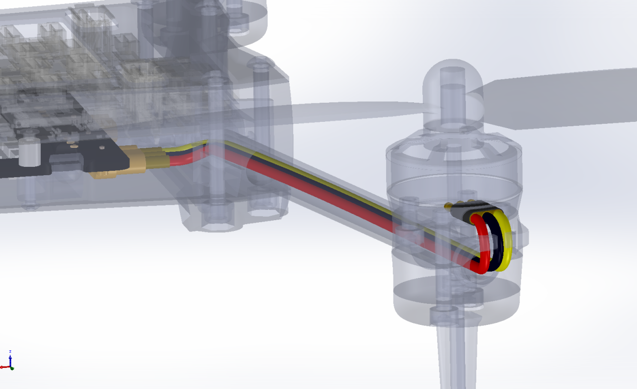
- Mechanical constraints like tight enclosures, bend radii, thermal zones, and accurate length calculations can no longer be solved in 2D. They require 3D validation to prevent costly assembly failures or long‑term wear.
- Bi‑directional ECAD–MCAD synchronization is essential, allowing engineers to eliminate manual entry errors, maintain accurate BOMs, simulate thermal and vibration effects, and enable concurrent engineering that avoids late‑stage design delays.
1. The Decadal Shift: High-Density Integration
Ten years ago, many electronic systems were characterized by modular, discrete functionality. Standard assemblies typically featured a primary control board and a limited number of peripheral connections. Engineering cycles were often linear; the electrical team designed the board, and the mechanical team designed a "box" to house it, with wiring treated as a late-stage installation detail.
Today, the landscape has fundamentally shifted. We have moved from simple devices to complex, multi-system architectures. Modern designs, particularly in the aerospace, medical, and defense sectors, are defined by high-speed data transmission, dense sensor arrays, and ultra-miniaturized components. The margin for error in physical space has disappeared, while the complexity of the interconnects has multiplied, forcing a move away from siloed engineering workflows toward integrated electromechanical environments.
2. The Rise of Complex System Architectures and the Wiring Explosion
Modern industrial, medical, and automotive standards now demand a level of "intelligence" and connectivity that was previously impossible. This is driven by high-performance embedded computing systems that act as the product's central nervous system. According to recent industry analysis, the global wire harness market is projected to reach approximately $118 billion by 2030, driven largely by the integration of advanced driver assistance systems (ADAS), avionics modernization, and the miniaturization of medical electronics.
As system capabilities increase, so does the demand for physical connectivity. In modern medical devices or aerospace subsystems, for instance, a single diagnostic hub or flight control unit can contain over 5,000 feet of wire and up to 1,000 distinct connections.
Management of these harnesses has become a primary design constraint; if the wiring is an afterthought, the system will likely suffer from assembly failures, signal interference, or thermal bottlenecks that can compromise mission-critical performance.
3. The Mechanical Challenge: Tight Enclosures and Mission-Critical Environments
While the electrical team defines the logical connectivity, the mechanical team faces the task of integrating that logic into increasingly hostile or constrained spaces. In sectors like wearable medical technology or aerospace, where weight and volume are the primary constraints, the "packing density" of electronics has increased by nearly 40% over the last five years.
This introduces critical variables that cannot be solved in a 2D environment:
- Spatial Navigation: In compact medical or defense hardware, harnesses must navigate "Z-height" constraints while avoiding contact with sensitive components, power sources, and antenna arrays.
- Bend Radii and Material Stress: High-performance cables in aerospace or medical robotics often require specialized shielding. Exceeding the minimum bend radius (typically 4 to 10 times the outer diameter) leads to micro-fractures in the shielding, resulting in catastrophic EMI compliance failure or signal degradation.
- Environmental and Thermal Zoning: Harnesses must avoid "hot zones." In dense enclosures, a temperature rise of just 10°C can reduce the lifespan of nearby critical components by 50%.
- Accurate Length Calculation: In high-precision manufacturing, an error of 10mm can result in a harness that is impossible to plug in or a bundle that sags, causing mechanical interference or vibration-induced wear during operation.
4. The Importance of Bi-Directional CAD Data Transfer
The bridge between a logical netlist (ECAD) and a physical 3D route (MCAD) is the most common point of failure. Industry data suggests that up to 20% of product development delays are caused by cabling and harness interferences discovered only during the physical prototyping stage.
Accurate synchronization between ECAD and MCAD is vital for several reasons:
- Elimination of Manual Entry: When electrical data (connectors, pins, wire types) is transferred natively, the risk of "fat-finger" errors is eliminated. This is critical for meeting stringent regulatory standards where traceability is mandatory.
- Real-World BOM Accuracy: 3D routing allows for the calculation of the exact physical length. This ensures the Bill of Materials (BOM) is accurate to the millimeter, preventing the 15-30% material waste commonly seen in oversized, "estimated" harness production.
- Thermal and Vibration Validation: Digital twins allow engineers to predict how a harness will behave under extreme vibration or how its physical presence affects airflow and thermal dissipation.
- Concurrent Engineering: Synchronization allows both teams to work in parallel. As the system architecture evolves, the mechanical team sees updated connectivity immediately, allowing them to adjust the enclosure or routing path before the design is finalized.
Conclusion
The "brain" of a modern high-performance system is only as reliable as the nervous system—the harness—that connects it. As systems across all industries become more sophisticated and compact, manual harness management is no longer a viable engineering practice. Organizations that prioritize seamless, accurate data transfer between ECAD and MCAD will reduce their time-to-market, eliminate costly re-spins, and deliver more robust, reliable products across the most demanding engineering sectors.
Want to seamlessly design wiring for your harness? Experience the power of wire harness design in Altium.
Frequently Asked Questions
Why is bi‑directional ECAD–MCAD data transfer essential for modern wire harness design?
Bi‑directional synchronization ensures that every change made in the electrical (ECAD) environment, such as connector selection, pin assignments, or netlist updates, is immediately reflected in the mechanical (MCAD) model. This eliminates manual transcription errors, prevents routing conflicts, and ensures that harness pathways, bend radii, and enclosure clearances are validated throughout development rather than during late‑stage prototyping.
What challenges make wire harness design so complex in aerospace, medical, and automotive systems?
Modern mission‑critical systems contain thousands of connections and extremely tight packaging constraints. Engineers must manage accurate cable lengths, safe bend radii, EMI‑sensitive routing, thermal zoning, and mechanical interference. A small miscalculation, such as a 10 mm length discrepancy or violating a cable’s minimum bend radius, can lead to assembly failures, EMI issues, or long‑term reliability risks.
How does 3D routing improve wiring accuracy and reduce development time?
3D routing tools calculate true physical wire lengths and visualize how cables move through the enclosure, across different planes, and around obstacles. This improves BOM accuracy, eliminates the 15–30% material waste caused by length overestimation, and reveals interference issues early, before a prototype is built. It also supports digital twin simulations for thermal, vibration, and airflow validation.
How can teams prevent wiring and harness issues from causing late-stage design delays?
The most effective approach is to adopt concurrent engineering. Electrical and mechanical teams work in parallel with live, synchronized models, allowing enclosure changes, PCB updates, and wiring revisions to be evaluated instantly. This reduces re‑spins, shortens the design cycle, and ensures that wiring constraints, such as connector placement, routing paths, and stress points, are validated continuously instead of after PCB completion.
Related Resources


Related Technical Documentation


Table of Contents
- Key Takeaways
- 1. The Decadal Shift: High-Density Integration
- 2. The Rise of Complex System Architectures and the Wiring Explosion
- 3. The Mechanical Challenge: Tight Enclosures and Mission-Critical Environments
- 4. The Importance of Bi-Directional CAD Data Transfer
- Conclusion
- Frequently Asked Questions
- Why is bi‑directional ECAD–MCAD data transfer essential for modern wire harness design?
- What challenges make wire harness design so complex in aerospace, medical, and automotive systems?
- How does 3D routing improve wiring accuracy and reduce development time?
- How can teams prevent wiring and harness issues from causing late-stage design delays?
Speed at Scale. Structured Repeatability. Secure Flexibility.
- Start up fast with out‑of‑the‑box workflows
- Collaborate using ECAD‑MCAD codesign tools
- Manage BOMs with live supply chain part data
- Manage access and security as teams scale
Contact Us
Thank you, you are now subscribed to updates.