BOM Control: Setting up your PCB Documentation for Success
Years ago I ventured into the world of remote control helicopters. Not the ready-to-fly-out-of-the-box drones that they sell today, but a gas-engine, Bell-Hiller mix, remote-controlled helicopter. What the salesman didn’t tell me though was about all the other items that I would need to purchase in order to complete it. I was going to have to purchase the engine, muffler, radio components, servos, starter, battery, as well as much more.
As you could imagine this didn’t go over very well with my spouse, and I can’t really blame her. A 3X cost overrun due to unplanned missing components is bound to make anyone a little cranky. In the same way, we also can’t blame our manufacturers when they get irritated at us for giving them a PCB bill of materials that isn’t complete enough to build a board with. An incomplete can cause a manufacturer a host of problems that will eventually come back to us in the form of delayed schedules, cost overruns, or bad builds.
The key is to make sure that your is ready to build your board before you send it out to the manufacturer. In this way, you won’t get surprised by missing or incorrect data. There are many opinions, and some debate, as to what is the most important data to include in the . The important thing to remember though is that you must provide enough information for your manufacturer to complete the assembly of your board without any problems.
The Critical Elements of a PCB, and Why they are Important
To ensure the success of your PCB, you will want to make sure that the basics are covered. To start with, the needs to have all of the components of the design included in it. Each component will be listed in the along with the following basic information:
- Part Number: This is the identification number for each component used in the design. Most companies use their own internal part numbering system. This will give them the ability to list the manufacturing part numbers as well as alternate manufacturing part numbers all under the same company part number.
- Reference Designator: This is the unique identifier for each individual component in the design.
- Description: This is a brief description of the component and can include information such as values and tolerances if they are not listed elsewhere in the .
- Package Type: This list the case or package type for that component.
- Quantity: For those designs whose BOMs are formatted to list each individual part as a separate line item, this field is either going to be a “1” or completely omitted. For BOMs that are listed by part number, this line will contain the total number of those components used in the design.
- Comments: This is your general “catch-all” field in the BOM to cover any further information that wasn’t detailed in the description field.
Additional Elements of a PCB
There are also many other elements that can be included in a PCB depending on the needs of the . For instance, a board that is being prototyped may not rely on an internal part number and instead default to a manufacturer’s part number instead. Here are some of those elements that may or may not get included that you should be aware of:
- Manufacturer’s Name: The name of who makes this specific component.
- Manufacturer’s Part Number: The manufacturer specific part number.
- Component Data: Some manufacturers want complete component data listed in the instead of being part of the general part description. Here is a partial list of some of that data:
- Value
- Voltage
- Current
- Power
- Tolerance
- PCB CAD Footprint: The CAD model used in layout for that specific component.
Make Sure to Include All of the Data for Complete Control
The data that the PCB layout tools provide to the should give you all of the regular electrical components. There may be some other components though that must not be forgotten to make sure that your PCB is complete.
The PCB may require mounting hardware that isn’t included as a regular electrical component inside of the CAD system. Also, you may find out that items such as labels and manufacturing stickers need to be added as well. Does your board have a battery on it? If so then the battery clip may be included as part of the data from the CAD tools, but was the battery itself included? These are a few of the “gotchas” that can cause your PCB to get stuck in the manufacturing process.
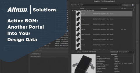
Fortunately, there are now PCB design tools that can provide solutions for making sure that your is complete and ready to go. These tools give you the ability to interact with the as part of the design process in the same way that you interact with the schematic or the layout. Instead of waiting for the design to be complete, you can work from within the tool to get access to part data, and you can cross-probe from there into the schematic and layout.
These tools are much more than simple report generators, they are part of the complete unified design environment as the schematic and the layout. For the advanced functionality that we have been talking about PCB design software like Altium will provide the experience you need. Active has been created to give you more control and power with your design.
If you’d like to know more about how your design software can make your whole design and production process more intuitive, begin by talking to an expert at Altium.


