How to Use a Multicad Viewer for Seamless Collaboration

At a Glance
Learn how a multicad viewer enables seamless collaboration, design reviews, and version control across ECAD tools without file migration or extra licenses.


The ECAD software world is peculiar in that it features a near total lack of file compatibility. ECAD files created in one application can’t be opened and modified natively in another application, instead requiring a “migration” process to convert the files between formats. This creates a problem for many companies in that they often maintain licenses for ECAD applications they no longer use; this is done simply to allow a company to open and view their old design files without requiring a full migration. This shows the need for better ECAD connectivity across tools.
In addition, today’s companies work with many external partners and customers, often with each actor using different tools. With design collateral available in multiple formats, companies should have a single tool that allows viewing multiple ECAD file formats and manufacturing files. A multi-CAD viewer provides exactly this function, creating a common space where all participants can interact with the same design and always work on the correct version.
What Is a Multi-CAD Viewer?
A multi-CAD viewer is a solution designed to display design files from different CAD ecosystems without the need to use the native tools with which they were created. Its purpose is not to replace ECAD, MCAD, or CAM software, but rather to provide a common and accessible environment where design information can be inspected, reviewed, and shared between different disciplines.
This allows you to examine schematics, PCB layouts, 3D assemblies, layer configurations, and manufacturing data without having to install the original software or pay for a license. These capabilities go beyond visualization, allowing you to interact with the design and improving the understanding of the complete design for other disciplines (electrical, mechanical, and manufacturing teams).
In addition, a multi-CAD viewer avoids versioning issues, as everyone is viewing the same version while maintaining the freedom of each team to work in their usual environment.
How to Use Altium Multi-CAD Viewer?
Although Altium is one of the most widely used ECAD tools, many companies use other tools such as OrCAD, PADS, Eagle, or KiCAD, among others, due to legacy issues, license costs, or their engineers' knowledge.
Altium Multi-CAD Viewer should not be confused with Altium's Import Wizard. The importer is capable of translating designs made in other environments and bringing them into the Altium Workspace. This solution is plausible when a redesign is required based on a project created in another tool.
But this is not always what is required. We often work with clients who do not have an EDA license, or we work with external collaborators (freelancers) who use KiCAD while we use Altium.
When it comes to design reviews, the task becomes more complicated. We request the latest version in PDF format, but it is not convenient to create comments in the PDF and associate them with tasks, and it is not easy to manage versions. For example, if there is a version change in the middle of a review and you are sent a new PDF schematic, you have to redo the comments. In other words, you need a tool that allows you to:
- Open a design made in another tool,
- Know that you are working with the latest version,
- Be able to share that same project with another team in order to properly review the design.
To do this, Altium allows us to upload a project from other environments, such as OrCAD, PADS, Eagle, or KiCAD to our Workspace.
In this article, we will look at an example with a design made in KiCAD to show how to upload the project, how to view it, and how to interact with the design.
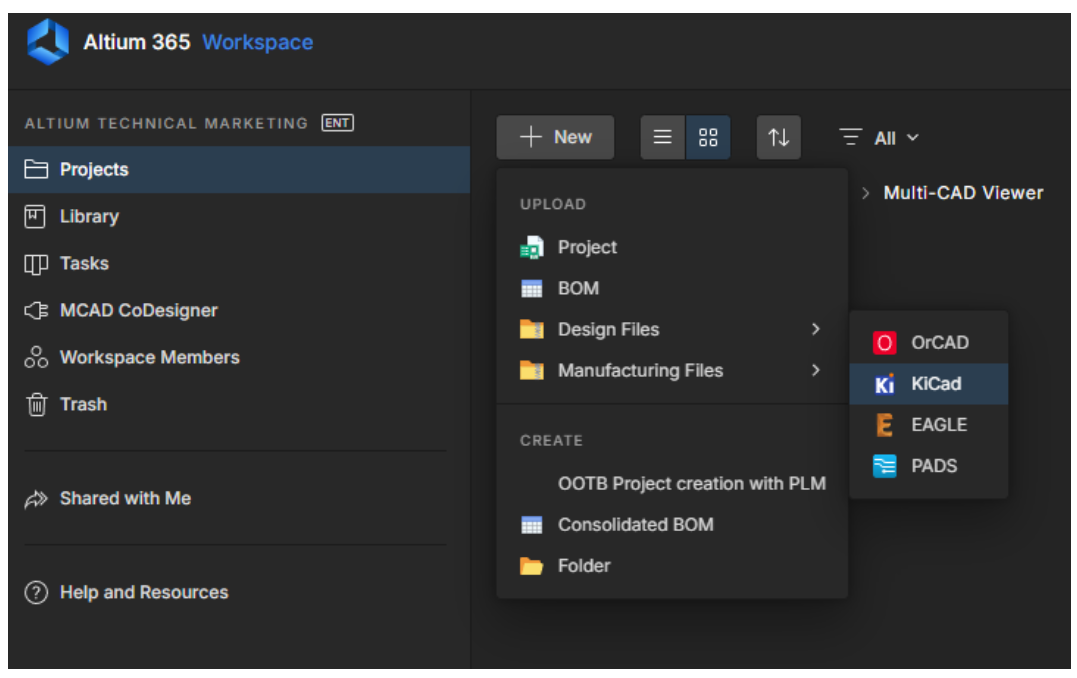
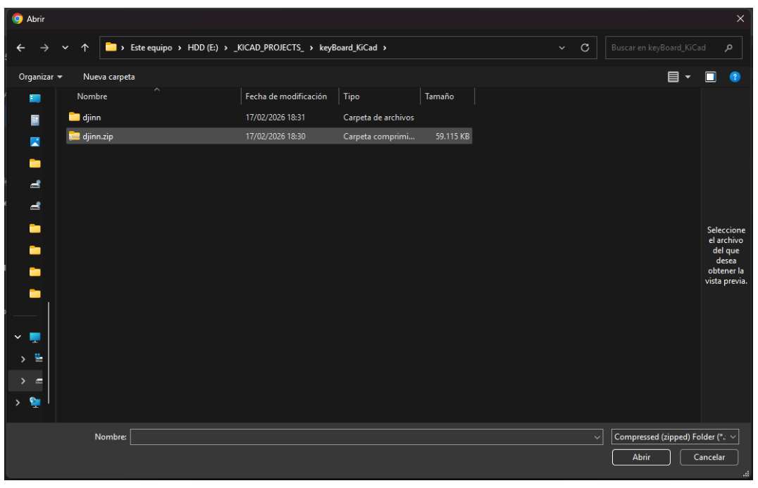
The first thing to do is to open the KiCAD project (which must be compressed in zip format). To do this, click on the button that says +NEW, select KiCAD in the option called Design Files, and click.
This opens a dialog box for selecting a project created in the KiCAD tool, as shown in the following image.
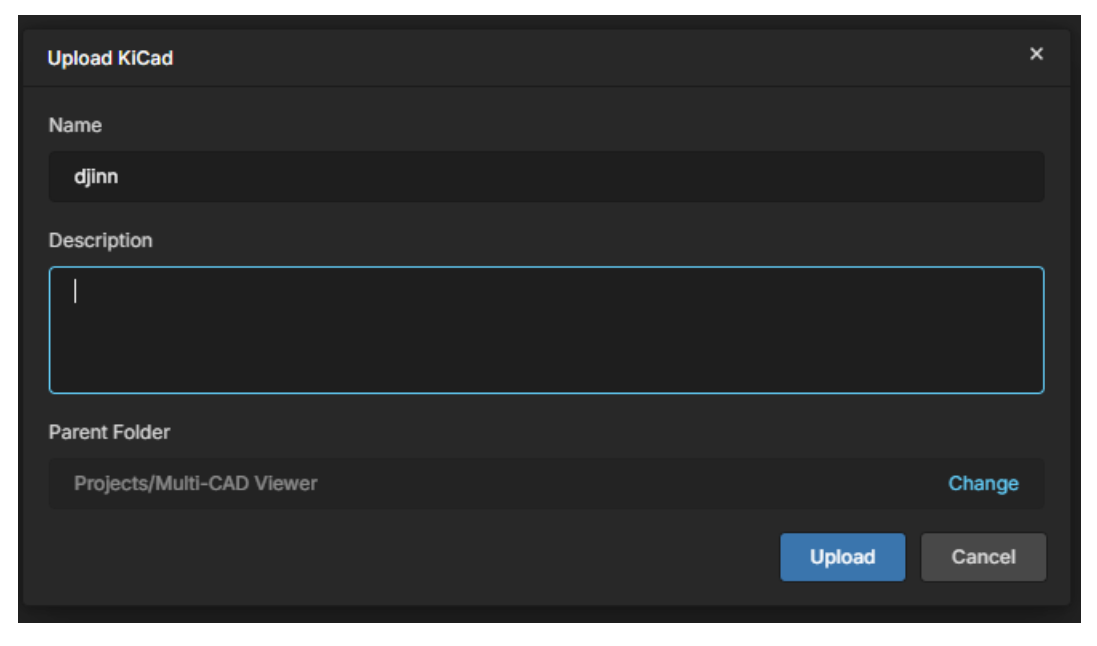
Once the project has been selected, a dialog box appears with the project name, a description that we can fill in with whatever we want, and the path where the project will be uploaded. We then click on the Upload button.
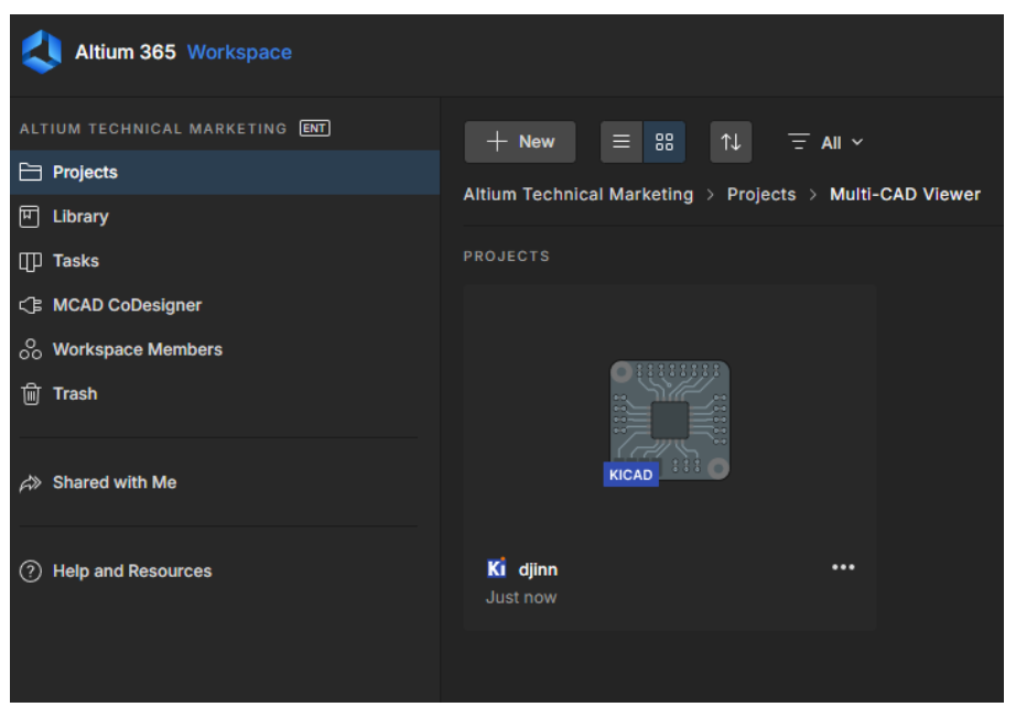
Once the project has been loaded into our Workspace, we should see something like the following:
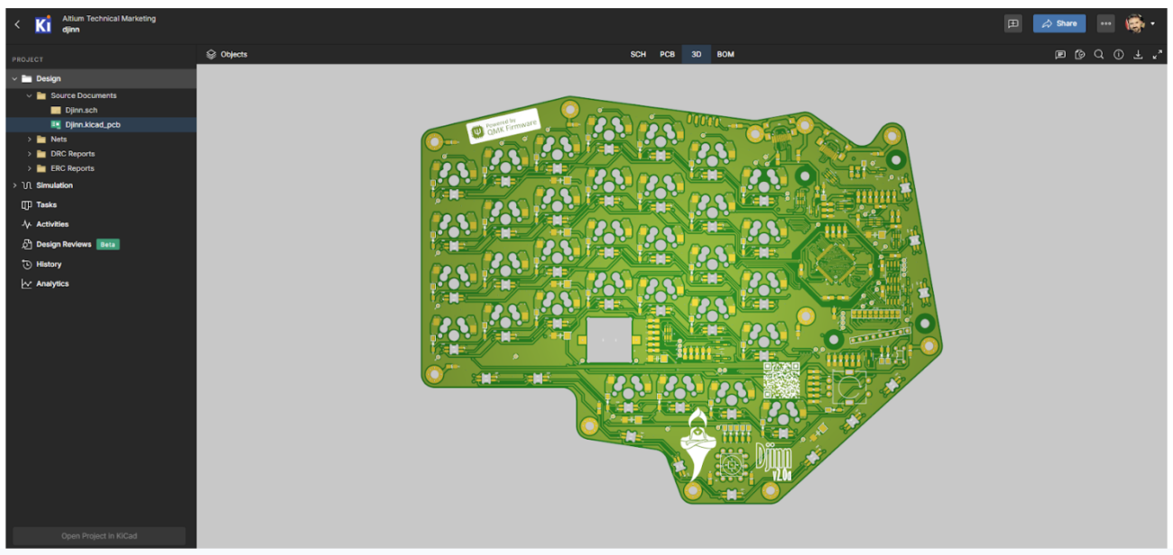
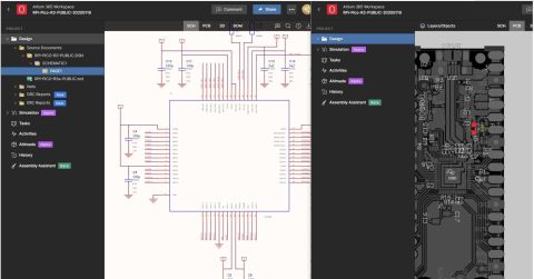
By double-clicking on the project uploaded to our Workspace, we can access the project and view the different files it contains, as shown in the following image:
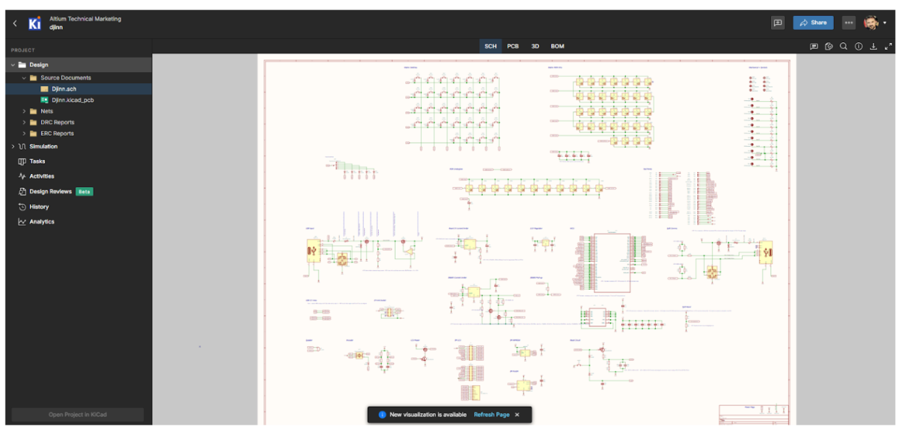
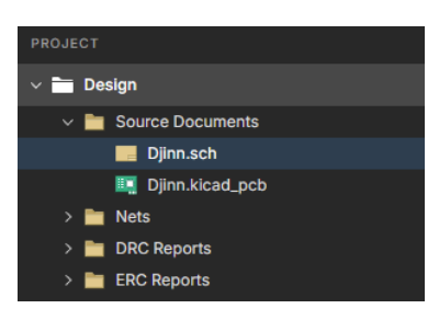
In the menu on the left (as in Altium Designer), we can see the project tree, with the different files it contains:
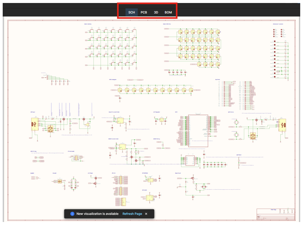
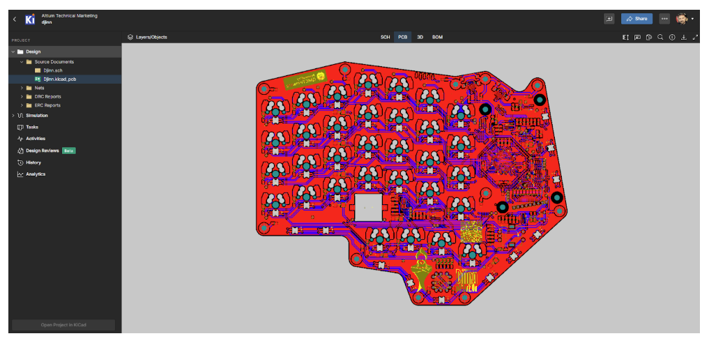
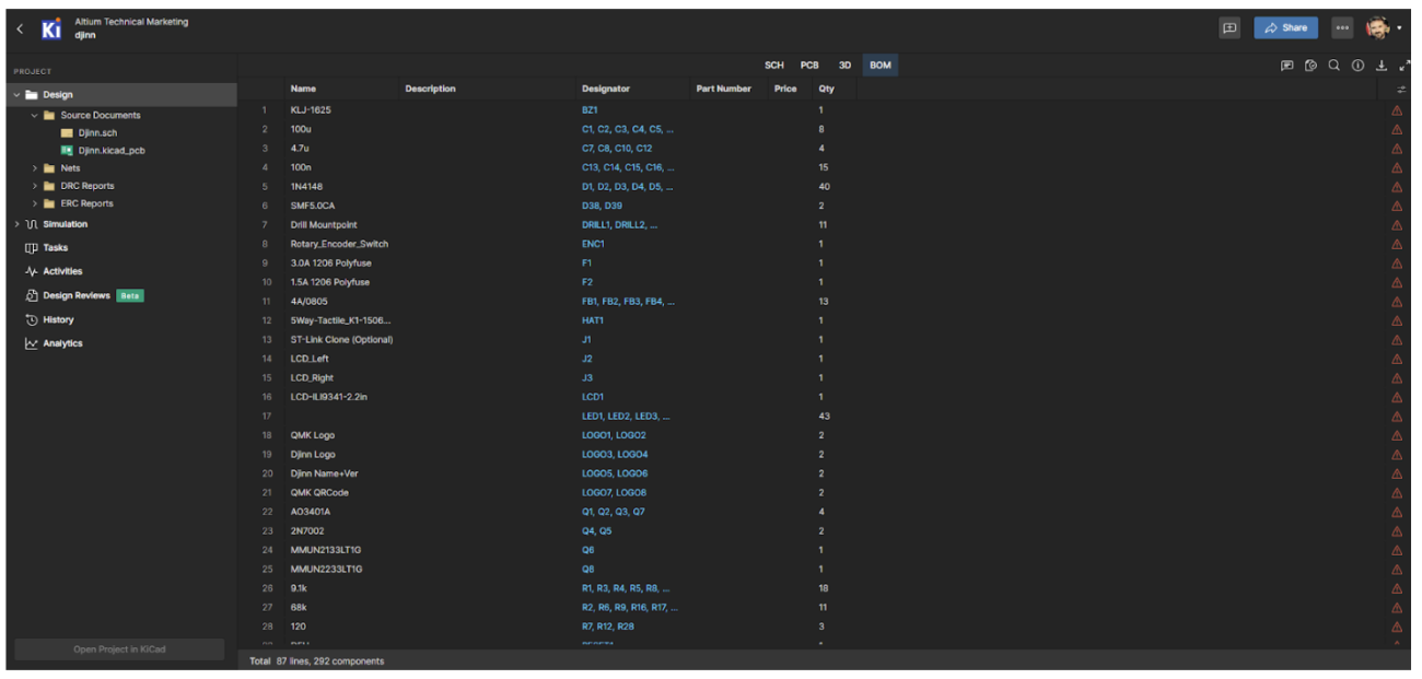
In the workspace, we also have buttons to directly access schematics, PCBs, 3D models, and BOMs:
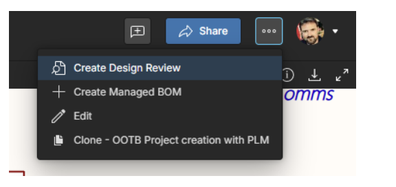
Now that we have the project loaded and have learned how to navigate through the different files, it's time to see how to create a Design Review. To do this, click on the three-dot button located in the upper-right corner and then select the Create Design Review option.
This opens a new work window, as shown in the following image.
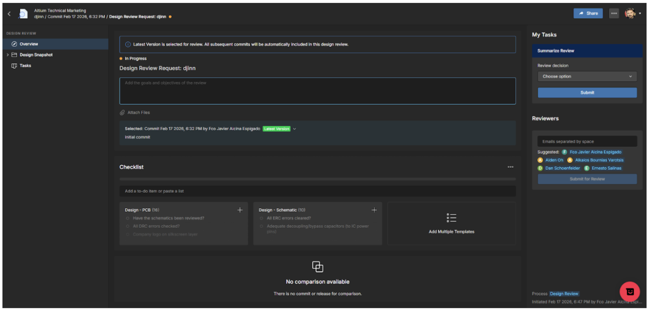
This is a very powerful tool that not only allows you to view the design made in another environment, but also to create a review, add comments, objectives, checklists, assign tasks to different team members, attach files, etc.
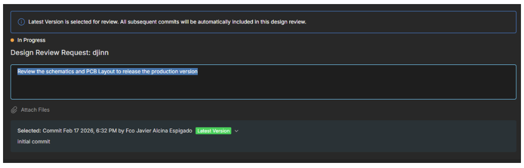
The first step is to create a review objective and select the working version.
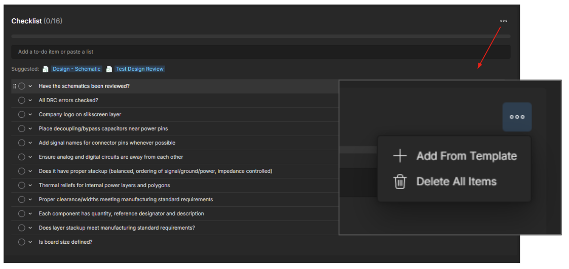
The second step is to create a checklist that includes all the points we want to review in the design. This checklist can be saved as a template and reused, with modifications as needed, for future reviews.
From here, we can start working on the different project files (schematics, PCBs, 3D, BOM) and check each item on the checklist while adding comments to the schematic and assigning actions to other team members. Let's look at an example:
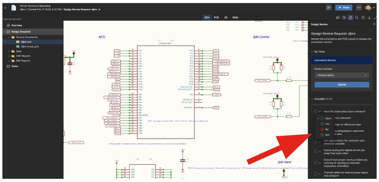
In the image above, the diagram is being reviewed, and in the menu on the right, we can mark one of the checklist options as Open, Yes, or No, or even N/A if this point of the checklist does not apply.
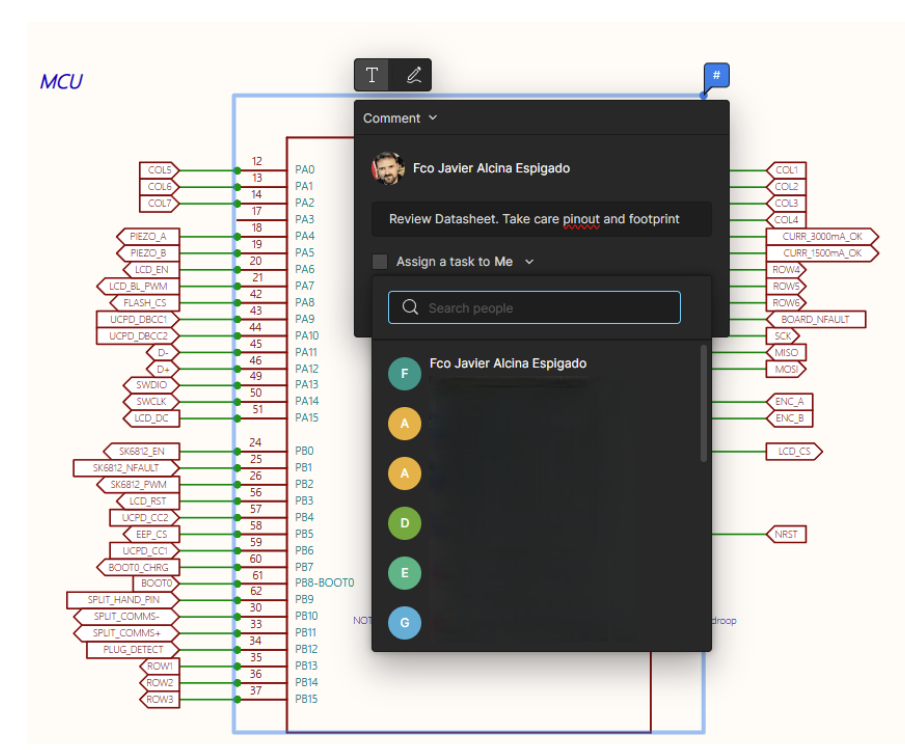
As we mentioned earlier, we can include comments anywhere in the document under review using the comments tool:
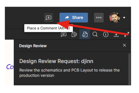
For example, we can leave a comment requesting a thorough review of a component's datasheet to avoid pinout or footprint errors and assign that task to a team member, as shown in the image below.
Similarly, in the PCB section, we can conduct a layout review, including a review of the stack-up.
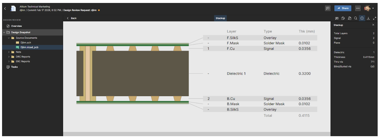
Of course, comments can also be added and tasks assigned here.
In short, Altium’s multi-CAD viewer is a powerful tool for viewing projects that were not created in Altium, allowing them to be viewed, reviewed, and worked on within the Altium environment to facilitate collaboration between different teams.
Conclusions
Today, electronic development is characterized by collaboration across different teams, disciplines, and tools. A common visualization and working method is required without compromising traceability or version control.
Altium multi-CAD feature addresses this need by providing a shared environment in which designs, regardless of the tool used to create them, can be viewed, reviewed, and discussed in a structured manner.
Altium also integrates review workflows, comment management, task assignment, and revision control within a single collaborative space. This eliminates reliance on static documents and significantly reduces the risks associated with outdated versions or ambiguous interpretations during the validation process.
The true value of Altium multi-CAD viewer lies in its ability to improve technical coordination between different electrical teams. By centralizing information and structuring the review process, communication is optimized, rework is minimized, and the quality of the final result is enhanced.
In an environment where designs are becoming increasingly complex and development cycles are growing shorter, a robust collaboration infrastructure is no longer an added benefit but a core element of modern engineering strategy.
Frequently Asked Questions
What problem does a multi-CAD viewer solve in ECAD workflows?
A multi-CAD viewer solves the problem of ECAD file incompatibility by allowing engineers to open, inspect, and review designs created in different ECAD tools without performing file migration or maintaining multiple software licenses. This enables teams to collaborate on schematics, PCBs, and manufacturing data even when partners or suppliers use different design environments.
Can I review ECAD designs without installing the original design software?
Yes. A multi-CAD viewer allows engineers to review schematics, PCB layouts, 3D models, and BOMs without installing the native ECAD tool or holding a license. This is especially useful for design reviews involving managers, manufacturers, or external collaborators who only need visibility and commenting capabilities rather than full editing access.
How is a multi-CAD viewer different from importing or converting ECAD files?
Importing or converting ECAD files translates a design into a new native format, which is typically required for redesign or editing. A multi-CAD viewer, by contrast, focuses on viewing, reviewing, and collaborating on the original design files without altering their structure. This avoids data loss, reduces risk, and ensures everyone is working from the latest version.
Is a multi-CAD viewer suitable for collaborative design reviews across teams and regions?
Yes. Multi-CAD viewers are designed to support collaborative design reviews by providing a shared, version-controlled environment where teams can add comments, assign tasks, and track review progress. This makes them well suited for distributed engineering teams working across different disciplines, companies, or geographic regions.

About Author
Related Resources


Related Technical Documentation


Table of Contents
- What Is a Multi-CAD Viewer?
- How to Use Altium Multi-CAD Viewer?
- Conclusions
- Frequently Asked Questions
- What problem does a multi-CAD viewer solve in ECAD workflows?
- Can I review ECAD designs without installing the original design software?
- How is a multi-CAD viewer different from importing or converting ECAD files?
- Is a multi-CAD viewer suitable for collaborative design reviews across teams and regions?
Speed at Scale. Structured Repeatability. Secure Flexibility.
- Start up fast with out‑of‑the‑box workflows
- Collaborate using ECAD‑MCAD codesign tools
- Manage BOMs with live supply chain part data
- Manage access and security as teams scale
Contact Us
Thank you, you are now subscribed to updates.