Complex Engineering Projects Leverage Multiple ECAD/MCAD Formats

At a Glance
Learn how complex engineering projects manage multiple ECAD and MCAD formats, maintain design authority, and enable effective PCB and enclosure collaboration.


Complex electronics products rarely originate from a single software environment. Reference designs may come from open source ECAD tools. Mechanical enclosures are defined in MCAD platforms. Manufacturing partners work from neutral fabrication data. Suppliers provide 3D models in yet another format.
Engineering teams do not choose multiple CAD formats as a strategy. They inherit them. The practical question is how to manage and use these formats correctly during each phase of development.
In complex projects, different CAD data types serve different technical purposes. Engineers must understand what each format contains, what it does not contain, and how it should be used.
Key Takeaways
- Complex electronics projects inherit ECAD, MCAD, and manufacturing formats from many sources (legacy designs, open source, suppliers, partners). Success depends on understanding what each format is for and using it appropriately at each development phase.
- Read‑only ECAD viewers are valuable for inspection, BOM extraction, and feasibility analysis, but they do not replace native ECAD environments where constraints, rules, and edits are actively managed. The authoritative design must remain in the tool where engineering intent is controlled.
- Effective ECAD–MCAD collaboration is about physical integration, not file conversion. Collaboration centers on exchanging geometry, clearances, connector alignment, stackup constraints, and component heights to ensure the PCB fits and functions inside the enclosure. This process is bidirectional and supports fit, clearance, thermal paths, and rigid‑flex behavior but does not replace dedicated simulation tools.
- Disciplined data ownership and revision control are critical in multi‑tool teams. Distributed teams succeed by defining master models, revision control rules, and controlled release processes, not by forcing everyone onto one CAD system. Clear authority over ECAD and MCAD data prevents version confusion, rework, and late-stage integration failures.
Working with Multiple ECAD File Formats
Modern PCB development frequently begins with legacy designs, evaluation boards, or open source projects created in different ECAD tools. Engineers may receive schematic and layout data in formats native to KiCad, OrCAD, Eagle, or other platforms.
In these situations, teams typically do one of the following:
- Open the design in a read only viewer to inspect layout, stackup, or component placement
- Extract a parts list for BOM comparison or cost evaluation
- Recreate or migrate the design into their primary ECAD environment
- Reference copper geometry, routing topology, or constraint strategy
Viewing foreign ECAD files is not the same as designing within them. A read only viewer allows inspection and data extraction, but it does not provide native editing, constraint management, or rule driven design control.
Engineers use ECAD file viewers primarily during evaluation and migration phases. For example, a design services company may review a client’s legacy project created in another ECAD tool. The viewer enables rapid assessment of layer count, impedance structures, fanout strategy, and component density before committing to a migration or redesign effort.
Extracting a parts list from a foreign ECAD project can also support early cost modeling. This is a data review activity, not an ECAD to MCAD collaboration function.

ECAD to MCAD Collaboration in Physical Product Development
Once a PCB moves beyond schematic capture and early layout, interaction with mechanical engineering becomes unavoidable. Mechanical constraints drive board outline, mounting hole placement, connector alignment, and keepout regions. Electrical constraints drive stackup, copper distribution, and component height.
ECAD/MCAD collaboration is focused on physical integration of the PCB within an enclosure or assembly. It is not a multi format viewer function. It is an exchange of geometry, constraints, and clearance data between two design domains.
A typical collaboration workflow includes:
- MCAD exports the PCB outline, mounting features, and component 3D models to ECAD
- Importing enclosure geometry, standoffs, and keepout volumes into the PCB layout environment
- Validating connector alignment and insertion depth
- Checking vertical clearance for tall components
- Iterating enclosure modifications when board thickness or stackup changes
This process is bidirectional in mature workflows. Mechanical engineers define internal volume and structural features. Electrical engineers define copper, dielectric stackup, and component placement. Each discipline updates the other as constraints evolve.
Accurate copper geometry modeling can influence thermal paths and mass distribution, but thermal simulation itself is typically performed in specialized analysis tools. The ECAD to MCAD data exchange provides geometry and material information that those tools rely on. It does not replace dedicated simulation environments.

Managing Z Axis Constraints and Component Height
As products become thinner and more densely packed, vertical clearance becomes a primary integration risk. Electrolytic capacitors, shield cans, connectors, and inductors often define the maximum board height. Mechanical engineers must ensure that enclosure ribs, lids, and fasteners do not conflict with these components.
The collaboration process typically involves:
- Assigning accurate component height attributes in ECAD
- Exporting 3D board assemblies to MCAD
- Performing clearance checks within the mechanical assembly
- Feeding interference results back into PCB layout
These checks are essential in medical devices, aerospace assemblies, robotics platforms, and any compact consumer product. Clearance errors discovered after tooling release can result in expensive redesign cycles.
Rigid Flex and Folded Structures
Rigid flex boards introduce additional coordination requirements. The PCB is no longer a flat structure. It may bend or fold into a three dimensional volume.
In these designs, engineers must:
- Define bend regions and allowable radii in the PCB stackup
- Provide mechanical teams with folded 3D representations
- Verify that flex regions do not interfere with enclosure walls
- Confirm that copper and coverlay transitions align with mechanical strain relief features
Mechanical stress analysis is usually performed in dedicated tools. The ECAD system provides the geometric definition of rigid and flex regions, while MCAD evaluates fit and mechanical interaction.

Decentralized Teams and Format Discipline
Large projects often involve external design firms, mechanical consultants, and contract manufacturers. Each participant may operate in a different CAD ecosystem.
Successful projects do not depend on a single unified platform. They depend on disciplined data exchange. This includes:
- Agreed upon revision control procedures
- Defined ownership of mechanical and electrical master models
- Controlled release of fabrication outputs
- Clear documentation of stackup and material selections
When multiple ECAD formats are involved, teams must also define which dataset is authoritative. A read only viewer copy of a legacy design is not the master file. The master resides in the native environment where constraints are actively managed.
The Role of Reference and Open Source Designs
Engineers frequently reuse reference designs published in alternative ECAD formats. These may include development boards, power supply modules, or RF front ends.
The workflow typically involves:
- Inspecting the original layout to understand routing and grounding strategy
- Extracting a component list for sourcing comparison
- Reimplementing the topology in the primary ECAD environment
- Applying updated design rules and stackup constraints
Directly editing a foreign format without constraint translation can introduce rule violations or manufacturing risk. Migration should be treated as an engineering task, not a file conversion shortcut.
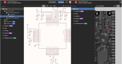
As projects grow and involve partners using multiple ECAD tools, Altium Agile Teams provides a practical way to manage that complexity without forcing immediate migration. Teams can bring designs created in tools such as KiCad, OrCAD, and Eagle into a shared Altium workspace for viewing, review, and BOM inspection, while preserving each project’s original file format. This makes it easier for electrical, mechanical, manufacturing, and sourcing stakeholders to work from the same up‑to‑date design context, review manufacturability and availability impacts, and coordinate decisions across formats.
By supporting multi‑CAD visibility inside a structured team workflow, Altium Agile Teams helps organizations reduce friction, avoid version confusion, and keep distributed contributors aligned as designs move toward manufacturing.

About Author
Related Resources


Related Technical Documentation


Table of Contents
Speed at Scale. Structured Repeatability. Secure Flexibility.
- Start up fast with out‑of‑the‑box workflows
- Collaborate using ECAD‑MCAD codesign tools
- Manage BOMs with live supply chain part data
- Manage access and security as teams scale
Contact Us
Thank you, you are now subscribed to updates.