NVIDIA Jetson Nano: Lane Detection and Tracking

Autonomous vehicles are slowly becoming an important part of the automotive industry. Many believe fully autonomous vehicles will soon be driving alongside humans, and technology companies are in a race to deploy fully autonomous vehicles. In December 2018, Waymo, the company that emerged from Google’s self-driving car project, officially started its commercial self-driving car service in the suburbs of Phoenix. Companies like May Mobility, Drive.ai, and Uber are following the same path.
Autonomous vehicles might seem to be a grand vision, but semi-autonomous vehicles are already among us. New Tesla cars have the Tesla Autopilot feature, which is capable of lane recognition and tracking, adaptive cruise control, and self-parking. The ability to identify and track lanes on the road is one of many prerequisites for driverless vehicles. While lane recognition may seem like a difficult problem, you can get started with developing lane recognition and tracking algorithms with the NVIDIA Jetson Nano hardware platform.
Intro to Jetson Nano
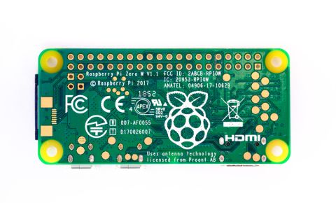
The Jetson Nano COM is slightly bigger than a Raspberry Pi 3, but it can run neural networks in parallel with 472 Gflops of power. This is about 22x more powerful than the Raspberry Pi 3 and is highly power-efficient, consuming as little as 5 W. This board is perfect for embedded AI applications running on a trimmed-down Linux kernel. It has enough processing power and on-board memory for high quality image and video processing applications. Key features of Jetson Nano include:
- GPU: 128-core NVIDIA Maxwell™ architecture-based GPU
- CPU: Quad-core ARM® A57
- Camera: MIPI CSI-2 DPHY lanes, 12x (Module) and 1x (Developer Kit)
- Memory: 4 GB 64-bit LPDDR4; 25.6 gigabytes/second
- Connectivity: Gigabit Ethernet
- OS Support: Linux for Tegra®
- Module Size: 70mm x 45mm
- The developer kit is a great tool for testing a new algorithm for computer vision/image processing applications. If you’re not familiar with the Jetson Nano platform, take a look at this article. Otherwise, keep reading to see how you can easily deploy a powerful image processing application for lane recognition.

Lane Recognition with Jetson Nano
For this project, we need a Jetson Nano COM or dev board and a CSI camera (a Raspberry Pi CSI Camera v2 works fine). I’ll show this application using the Nano dev board, but you can easily build a custom baseboard for a Nano COM and deploy this application. The CSI camera will be connected to the camera port on the Jetson Nano, although you could use a USB camera or IP cameras. Below are the necessary requirements to get this project to work successfully:
Hardware
- NVIDIA Jetson Nano
- CSI Camera
Software Packages
- Python
- OpenCV
- Nanocamera
Implementation
The full implementation for this project can be found on GitHub. Follow through the forthcoming steps to get a demo of this project up and running. These steps are important image processing steps that are intended to make lane recognition more accurate.
Perception
The first step of our lane detection system is being able to read live images from the camera. For new users working with the Jetson Nano, working with the cameras might be tricky. For this, we will be using the NanoCamera library. This library is not the best option for a production-grade application, but it works for a simpler application like that shown here.
First, install the library with pip:
Reading the live image from the camera:
Remove Noise with Blur
To make the image smoother and remove unwanted noise, we can apply Gaussian blur. This involves calculating each pixel’s value as a weighted average of the surrounding pixels.

OpenCV includes a function for applying Gaussian blur to an image:
Color Transformation
After the Gaussian blur, the image is still in RGB and must be transformed into HSV color space. Color separation will be used to remove unwanted colors from the image. Once the image is in HSV, we can “lift” all the unnecessary colors from the image by specifying a grayscale range.
Morphological Operations - Dilation
Dilation adds pixels to the boundaries of objects in an image. Applying dilation to the image will help close any loose spaces in the line images.
Canny (Edge Detection)
To detect lane lines, we can use a technique called Canny edge detection. Canny edge detection can be used to extract useful structural information from an object. The OpenCV library provides a Canny edge detection function that can be used to detect edges in an image. For Canny detection to work, we need to supply minimum and maximum thresholds. OpenCV usually recommends the value to be (100, 200) or (200, 400), so we are using (200, 400).

Isolate Region of Interest
The Canny edge output image contains some noise. All information other than lanes in the image can be isolated by reducing the region of interest. When performing lane recognition and navigation, we don’t necessarily need to see the entire image. An easy way to do this is just to crop out the top half of the image.

The code for reducing the region of interest is:
Detect Line Segments - Hough Lines
After the region of interest was reduced, the lanes are clearly visible with four distinct lines. However, the computer doesn’t know that these lines represent the boundaries of two lanes. So, we need a way to extract the coordinates for these lane lines. A Hough transform is a technique used in image processing to extract features like lines, circles, and ellipses. It can be to find straight lines from a number of pixels that seem to form a line. This can be done with the HoughLinesP function in OpenCV. The function fits many lines through all white pixels and returns the most likely set of lines subject to some minimum threshold constraints.

Here is our code that detects line segments using a Hough Transform. Most of the parameters used here can be determined through trial and error or by selecting parameters from reference images.
Combine Line Segments into Two Lane Lines
The output of the detect_line_segments() function produces a set of small lines with endpoint coordinates (x1, y1) and (x2, y2). We need to find a way to combine them into just two lines for left and right lane lines, but how do we achieve that? One way is to classify these line segments by their slopes.
All the left lane lines have a positive slope, and the line segments belonging to the right lane line have a negative slope. Based on these two new groups, we can take the average of the slopes and intercepts of the line segments to get the slopes and intercepts of the left and right lane lines. This is implemented with the average_slope_intercept() function:
The make_points() function is a helper function for the average_slope_intercept() function, which takes a line’s slope and intercept, and returns the endpoints of the line segment. At this point, we now have the lane lines!
What’s Next
At this point, the output from this function would be input to another algorithm for controlling the speed and heading of the vehicle. In order to do this, a steering angle can be computed from the detected lane lines and then passed to a PID controller to minimize the steering angle and keep the vehicle centered.
Although this was done with a Nano dev board, the same code provides a starting point for deploying a system in an embedded image processing system for a production environment. To do this, you’ll need to build a real baseboard for the Jetson Nano. This is easiest when you use the modular electronics design tools in the Upverter Board Builder application. By taking a modular approach, you can easily customize a baseboard for a Jetson Nano, cameras, and other sensors for lane recognition.
The modular electronics design tools in Upverter give you access to a broad range of industry-standard COMs and popular modules without downloading or installing any new software. You can create production-grade hardware for a variety of applications, including lane recognition and other image processing tasks with Jetson Nano, using a drag-and-drop user interface. If your system needs additional functionality, you can include wireless connectivity, an array of sensors, and much more.
Take a look at some Gumstix customer success stories or contact us today to learn more about our products, design tools, and services.


