


Low-Cost Verification for Digital and Analog Filters


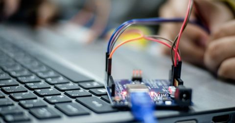
In Low Cost Solutions for Automated Hardware in the Loop Testing, we reviewed the idea of using low-cost testing devices to validate our hardware designs. In this article I want to zoom in on a specific application that can have a high barrier to entry when it comes to verification: Digital Signal Processing (DSP), specifically signal filtering. Rather than belabor the topic of DSP I will define it simply as “digitizing signals that come into your board and then doing stuff with it.” For a more in-depth understanding of what DSP is and how it works, you can consult Wikipedia or various tutorials such as dspGuru or DSP Guide. The focus of this article is to find a simple, yet cost-effective way to validate your digital (or analog) filters. For simplicity, I have implemented my digital filter using an Arduino. The code repository can be found here.
The Baseline
It’s pretty common to see that the closer one gets to the electrons the more primitive the testing is. This isn’t an attack aimed at the analog design community. It’s reasonable to expect little or no test automation for non-production-based hardware. As discussed in Test-Driven Development for Embedded Systems on OnTrack there hasn’t been much of a driving factor for electrical engineers to automate the full suite of tests to validate their design at the development stage. The cost and time that it requires just don’t justify the few times the engineer needs to turn a few knobs and call it good. Enter analog and digital filtering. A basic filter designed perfectly can be verified by the design engineer once or twice and handed off to the next stage in the design pipeline. When multiple variables enter the equation such as tuning, range verification, and EMI testing, automation helps tremendously. Most high-end oscilloscopes come with some sort of spectrum analyzer that can perform Fast Fourier Transforms (FFT) for you to determine if your filter is working properly but very few are fully automated. For that, you will usually need a companion set of software (e.g. LabVIEW or custom software using your manufacturer's provided libraries).
Let’s look at a simple example: a low pass filter attempting to filter out all frequencies above 100 Hz with a specific noise rejection level. If I want to test this manually I will compare my input against the output while varying the input frequency and amplitude that I am driving out of my function generator. A sample test setup would usually look like this:

Even if we stick with whole numbers testing every single frequency would take a very long time. Using a lower-end Tektronix oscilloscope I tested just 4 different frequencies and it still took me some time to configure my oscilloscope, drive the inputs manually, and capture the images of each waveform. As you can see the image captures aren’t very high resolution either.


The scope captures and definitely demonstrates that the filter seems to be working. You can see that the filtered signal (Channel 2) slowly attenuates as we approach 100 Hz, achieving our requirement of “filtered out” as it hits that target. The same can be said about the built-in FFT math function that comes along with the oscilloscope. It’s nothing to write home about but it does get the job done for an oscilloscope that cost me about $1,,000.

When we go through this process, especially after the tenth round of rework, we have to ask ourselves, “How many times are we willing to manually verify our designs like this?”
Verification Trade Space
When it comes to verification and automated testing, especially with more complex designs that include digital signal processing, we need to understand where to invest the time and money in automation. Let’s look at three different viable options that we have for testing our filter designs.

The first option, as we saw earlier, uses an oscilloscope and function generator. These are standard tools that every engineer learns how to use in school. It’s manual, tedious, and not very thorough. The second option, capturing the data and processing it, is great but only if you’re good with MATLAB or SciPy. The last option is good as well but also requires an understanding of the device you’re using (or the drivers associated with the device).
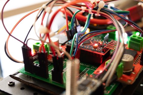
For this project,, I took a mixed approach. I first visually verified everything using my Analog Discovery 2 and then moved to automated verification using Python’s Pytest framework.

Once I set myself a baseline I moved on to automated verification. My CI/CD setup consisted of two stages: Compile/Load firmware and Hardware in the Loop testing.

Between these two scripts a total of three tests had been executed and reported back to Gitlab. These tests were run on a hardware target using a Gitlab Runner that I had configured on a computer (or Raspberry Pi).

My test objective was to ensure that my input signal had been properly attenuated at frequencies greater than 100 Hz and my automated test did exactly that.

I implemented a “poor man’s version” of an amplitude checker by slicing the edges of my wave and grabbing the first few max and min values of my sine wave. Note that in real DSP one would need to apply a window function and then run an FFT on the filtered signal. For this test I only cared that my input amplitude of 1V has attenuated down to 0.2V or less for frequencies above 100 Hz. As you can see in the job log this test did exactly that. We can now take this test suite and run it anywhere without having to manually set up our equipment every time.
Conclusion
In this article we introduced the topic of digital filtering (as part of DSP) and how to test such designs. Moreover, we reviewed the concept of testing filters manually and in an automated fashion. By using the proposed setup and test scripts the designer can skip the manual setup/testing and leverage automated verification.
Would you like to find out more about how Altium can help you with your next PCB design? Talk to an expert at Altium or discover more about the top DFM problems and their solutions.
About Author
Related Resources
Related Technical Documentation
Table of Contents
Design to Release, Without the Friction
- Keep reviews tied to the right version
- Reduce handoff confusion and rework
- Spot sourcing and release risk earlier
- Work solo, share when needed
Get Started
Thank you, you are now subscribed to updates.


