


Standard vs. Specialized Component Selection in PCB Design

At a Glance
Choosing the right components for your PCB circuit. Standard vs. Specialized Component Selection in PCB Design. Find out more.


Some overseas production services try to keep things extremely easy for designers by limiting their inventory to a small set of “standard” components. While the intention is to make it easy for designers to make purchases, the distinction between “standard” and “specialized” is vague. I think there are two areas that distinguish standard and specialized parts: how specialized components impact certain design designs in the PCB layout and how the parts conform to more advanced standards.
What Makes a Component "Specialized"
A common misconception is that specialization is purely about electrical capability, as if a part becomes specialized simply because it integrates more functions or operates at higher frequencies. In practice, a part becomes specialized when selecting it forces narrower constraints on manufacturing, sourcing, inspection, compliance, or system integration than a commodity alternative would.
Several factors drive specialization beyond electrical performance. Parts that integrate multiple system functions, or which force more advanced layout techniques, could be considered "specialized." Package type is another driver: for example, leadless packages like BGAs, QFNs, and LGAs may require X-ray inspection instead of standard AOI, raising assembly cost and process risk even when the electrical function is straightforward. Very small passives such as 0201 or 01005 sizes require handling and assembly expertise, whcih of course increases placement attrition and yield risk, making the assembly process more specialized regardless of the component's electrical simplicity.

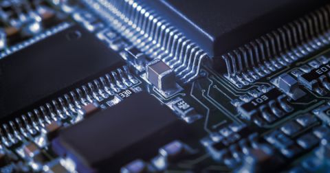
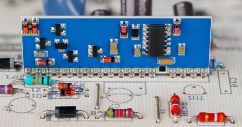
These RAM chips are a classic example of a specialized component that drives specific PCB layout practices and requirements.
Next, there is something not often considered by designer working in certain regulated industries where there are expectations of reliability. For example, aerospace and automotive components and connectors require specific testing to prove conformance to safety and functional standards. These components are more specialized in that they are less-often used due to their lower availability and higher cost (the latter mostly due to manufacturing and testing). So in summary, there is no specific category for "specialized" components, technically anything could deserve that description.
Selection Criteria Beyond the Datasheet
Choosing between standard and specialized components requires evaluating factors that do not appear on a datasheet but directly affect producibility and program risk. The following criteria should be assessed during schematic capture, not deferred to procurement:
- Footprint compatibility across alternates: If supply risk exists, prefer components where multiple manufacturer part numbers share the same footprint, so alternates can be qualified without a layout respin.
- Assembly process requirements: Determine whether the component requires special reflow profiles, underfill, X-ray inspection, or nitrogen atmosphere. Each of these adds cost and limits your choice of contract manufacturer.
- Fabrication capability coupling: Evaluate whether the component's package drives the board into HDI, sequential lamination, or laser-drilled microvias. If it does, confirm that the added fabrication cost and lead time are justified by a system-level requirement, not just a preference for a smaller package.
- Qualification and compliance status: In regulated markets, specialized parts may require additional qualification testing, lot traceability, or controlled-change agreements. Standard parts with established qualification data reduce this burden.
- Lifecycle and obsolescence risk: Specialized parts from smaller suppliers or with narrow application markets are more likely to face end-of-life notices. Designing in a standard part with a broader customer base reduces the probability of a forced redesign.
How Pricing and Availability Data Influence Schematic Capture
Pricing and availability are not procurement concerns to be addressed after layout. They are design inputs that should influence architecture and component decisions during schematic capture. Ignoring them at this stage is how programs end up with BOMs that cannot be built on schedule or within budget.
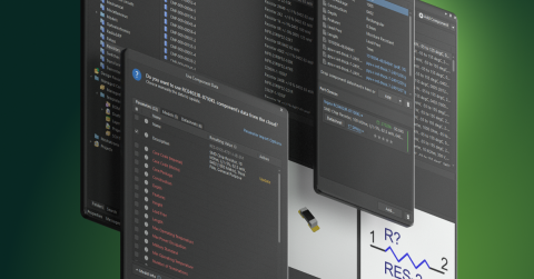
When a preferred IC is supply-constrained or single-sourced, it is often cheaper and faster overall to select a slightly less integrated but more available alternative than to complete a layout and then redesign under schedule pressure. This is an architecture decision, not a sourcing decision, and it belongs in the schematic capture phase. Live BOM cost visibility during capture also prevents the common failure mode where component cost dominates total product cost but is not evaluated until after routing is complete. If the design tool carries dynamic pricing and availability data, the designer can monitor cost trends and switch to lower-cost options before those changes require layout modifications.
Assembly model decisions are also influenced by component availability. If the program plans to use turnkey assembly, component markup from the assembler must be factored into the BOM cost estimate. In some cases, turnkey still wins over consigned builds because it eliminates logistics overhead and attrition management, but that calculation depends on the specific components selected. For very small passives where placement attrition is high, the effective BOM cost per build can be significantly higher than the unit price suggests, which may justify selecting a larger package size where the design envelope permits.
| Factor | Standard Component | Specialized Component |
|---|---|---|
| Unit cost | Lower, competitive sourcing | Higher, fewer suppliers |
| Lead time | Shorter, broader distribution | Longer, allocation risk |
| Footprint alternates | Multiple MPNs share footprint | Often unique footprint |
| Assembly process | Standard SMT | May require X-ray, underfill, or special reflow |
| Fabrication impact | Conventional stackup sufficient | May force HDI, microvias, or tighter design rules |
| Qualification burden | Established data available | May require additional testing |
| Lifecycle risk | Broad customer base, longer life | Narrower market, higher obsolescence risk |
| Layout flexibility | Easier to reroute or substitute | Substitution may require respin |
Reliability Requirements and Component Derating
Reliability specifications in regulated or mission-critical products directly constrain component selection. When a system must meet a defined mean time between failures or operate within a specific reliability class such as IPC Class 3, the designer cannot simply choose the lowest-cost part that meets the electrical specification. Derating requirements force the selection of components rated well above the nominal operating conditions, which often pushes the BOM toward specialized or mil-grade parts.
The downstream effects are significant. Higher-reliability components typically cost more, have longer lead times, and may come in packages that require more board area or more complex assembly processes. These constraints must be visible during schematic capture so the designer can make informed tradeoffs between reliability margin, cost, and manufacturability. Deferring this analysis to a later design review stage risks discovering that the selected components cannot meet the reliability requirement without a board respin or a BOM restructure.
Designing for Substitution
The most resilient designs anticipate component substitution from the start. This does not mean designing for the lowest common denominator. It means structuring the schematic and layout so that when a component becomes unavailable, over-budget, or end-of-life, the substitution does not cascade into a full redesign.
Practical strategies include selecting passive component values from standard series rather than specifying unusual values that limit alternates, using common footprints where multiple manufacturers offer pin-compatible devices, and documenting approved alternates in the BOM during initial release rather than scrambling to qualify them during a shortage. For ICs, this may mean choosing a device family where multiple speed grades or feature variants share the same package and pinout, giving the program flexibility to adjust performance or cost without touching the layout. The goal is to keep the design adaptable to supply chain disruption without sacrificing the performance requirements that justified the original component selection.
To learn more about component selection, read this related article or watch the video below.
Whether you need to build reliable power electronics or advanced digital systems, use Altium’s complete set of PCB design features and world-class CAD tools. Altium provides the world’s premier electronic product development platform, complete with the industry’s best PCB design tools and cross-disciplinary collaboration features for advanced design teams. Contact an expert at Altium today!
Frequently Asked Questions
What makes a component specialized in PCB design?
A component is specialized when it creates tighter manufacturing, sourcing, inspection, or compliance constraints than a standard alternative. It is not just about electrical performance.
Can component selection force HDI stackup requirements?
Yes. Fine-pitch or complex packages can force HDI, microvias, or sequential lamination. That only makes sense when the system requirement justifies the added cost and lead time.
When do reliability requirements require higher-grade components?
They matter when the product has explicit reliability, safety, or compliance requirements. In those cases, derating can push the design toward higher-grade or specialized parts.
How can designers plan for component substitution without a respin?
Choose standard values, shared footprints, and device families with pin-compatible variants. Approved alternates should be defined in the BOM from the start.

About Author
Related Resources
Related Technical Documentation
Table of Contents
Design to Release, Without the Friction
- Keep reviews tied to the right version
- Reduce handoff confusion and rework
- Spot sourcing and release risk earlier
- Work solo, share when needed
Get Started
Thank you, you are now subscribed to updates.

