PCB Designer Responsibilities: How to Manage Engineering and Manufacturing Expectations
My wife works at an elementary school, and the thing she dislikes the most is when she has to put herself between two kids in an argument. Being caught in the middle like that is frustrating for her because it is often difficult to turn it into a “win” for both sides of the argument.
We as PCB designers are often in the same position when we have to mediate the needs of electrical engineering and mechanical engineering. Trying to negotiate a “win” for both sides can be one of the most difficult things that we have to do. We are the “no man’s” land between two sides of a war, and it is our job to come up with an amazing board design that satisfies both sides. To do that we need to find ways to get both sides working together. Here are some ideas on how we can best do that.
Improve communications
The first thing that we can do to help the relationship between electrical engineering and manufacturing engineering is to improve communications between them. I know that it’s tempting to avoid the conflict by burying our heads in the sand and focus on routing traces. Ultimately though, our goal is to produce the best design possible. The only way we are going to be able to do this is to get these two groups communicating instead of fighting against each other.
Encouraging participation in the design process by both groups is a great way to improve communications. I have seen companies where people felt unattached and left out of the design process resulting in an “us versus them” mentality. This usually happens because the people don’t know each other, are unsure of who has what responsibilities, or are blocked by antiquated corporate policies.
To open up communication in situations like this, get these people involved. Ask for their opinions on what you are doing, and make sure that regular design reviews are scheduled. If someone isn’t part of the review that should be, get them on board. Finding out that a design failed due to a missed detail because a key person was absent during the design process is a tragedy. On the other hand, I’ve personally experienced the success that you can have when all team members are freely giving input during the design.
Document the DFM processes
Another way that you can help the relationship between electrical engineering and manufacturing engineering is to make sure that your company’s DFM processes are documented. This way everyone has a clear understanding of what the design objectives are.
There is a vast difference in how the design for manufacturing (DFM) processes are documented amongst companies. Some are very detailed and available online, or in some sort of printed format. The designs at these companies are often gated to the DFM documentation and won’t be released without the proper authorization. Then on the flip side there are those companies who have little if anything in the way of documented DFM practices. If DFM practices are followed at all it is usually in the form of “tribal knowledge” based on previous manufacturing experiences.
So how can you help in this documentation process? First of all, make sure that you are fluent with your company’s current DFM documentation. If your company doesn’t have any DFM processes documented, start working on them yourself. A good place to start is by collaborating with your company’s manufacturing engineers or your manufacturing vendors. Researching industry established manufacturing specifications is another good way to gather information. The important thing is to start capturing these standards and get them documented. Even if all you do is to just create some simple “bullet-points” in a text document, it’s a good place to start.
Check for DFM compliance in design before going to manufacturing
Even by following the rules, there can still be some DFM errors that get missed in design. Because DFM checking is traditionally done in manufacturing, electrical engineering usually isn’t aware of those errors until notified by manufacturing. With the design being kicked back and forth between groups for checking and correction, there is yet another opportunity for friction between departments.
With DFM checking tools readily available, you should run these checks first before you send the design to manufacturing. Some PCB design tools have DFM checking functionality built into them in addition to their regular DRCs. There are also plenty of third party checking tools available as well. By participating in the DFM checking, your electrical engineers can learn what manufacturing is looking for and correct those problems before they get to the manufacturing floor. Not only will this save the time and money that would be spent on bad boards and re-designs, but it will also help in getting everyone working together.
Use an online PCB Bill of Materials
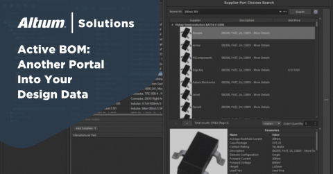
Another great way to improve cross departmental communications is for all departments to have live access to an online PCB bill of materials. Manufacturing can use it to plan ahead for parts in upcoming designs. Engineering can see real-time stock inventories and post online part requests. BOM management tools can provide this online service which will eliminate the time, errors and waste of traditional paper documentation processes.
As designers we have a big job ahead of us trying to satisfy the requirements of both electrical engineering and manufacturing engineering. Fortunately though there’s a lot of help out there for us to successfully negotiate a win for both sides of this conflict. PCB design software, like Altium Designer, has enhanced features that can help you design for DFM compliancy. Would you like to find out more about how Altium can help your design needs? Talk to an expert at Altium.


