


Successful ECAD/MCAD Collaboration Practices


In this article Zachariah Peterson, founder of Northwest Engineering Solutions, discusses how his company successfully collaborates with mechanical engineers outside of his firm. He shares practices and tools that have been most useful along the way.
Judy Warner: Zach, as an engineer and the owner of Northwest Engineering Solutions (NWES), what challenges do you see as most prevalent and problematic for design engineers when it comes to integrating the sometimes disparate requirements of mechanical and electrical engineers working on the same device or system?
Zachariah Peterson: There’s a lot of back-and-forth between the mechanical designer and the electrical designer. When I got started doing PCB design, it was mostly layout jobs. We would get a set of schematics and a board drawing, maybe a DXF file with some holes and connectors placed, and everything else was up to us to do the layout and routing. Now, we’re much more involved in overall product development, and my most frequent interactions with clients is with their mechanical design engineers. They need to see the board and we need to see the enclosure. It’s a lot of back-and-forth, and it’s almost never a situation where we just send a 3D model for a board and they just build the enclosure.
Warner: What tools or processes do you think help create the best solutions and outcomes from both sides of this engineering “fence”?
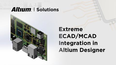
Peterson: STEP files have saved us so many times. The ability to quickly export a STEP file and send it off for review is a big time saver. There’s also the need to access the mechanical design directly and import your PCB into that MCAD application.
Warner: You wrote an article last year about pressure-sensitive electronics and the additional variables and impact that had on the overall design. What other applications or environments introduce additional complexity for the mechanical and electrical engineers?
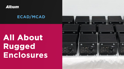
Peterson: Anything with confined space that is not well-defined can be difficult. As an example, we’ve done projects for devices that mount in enclosures with only one access point for power and data. The enclosure is a big part of these products, and you have to come up with unique ways to access the board inside its enclosure without compromising on requirements like connector placement, mounting location, etc. The list of requirements you have to balance can be really long, and oftentimes many of those critical requirements are mechanical and environmental.
Warner: I think most people think of fitment of enclosures when it comes to MCAD, but not creating accurate 3D component models. What can go wrong if careful attention is not given to this part of the design?
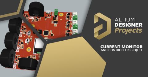
Peterson: I’ll give an example. We just did a unique board where the customer had some interesting USB plugs pointing horizontally across the board, and there was a group of tall capacitors nearby. Thankfully, we saw that these capacitors would make it very difficult to plug in a cord into one of the USB plugs and they needed to be moved. If we didn’t have 3D models attached to the component, there’s no guarantee that anyone would have noticed that problem. There are many other collision scenarios involving components that are easy to spot in 3D, but you might miss these if you started comparing component sizes from datasheets.
Warner: Until recently, collaboration between mechanical and electrical engineers has been challenging due to the dissimilar nature of the file formats, and the need to exchange files back and forth in a way that can lead to mistakes. What are methods that help ensure accuracy and reliability between each stakeholder?
Peterson: We rely on the mechanical engineer to understand how components fit onto a board and how boards are designed to mount to enclosures; that way, they can properly design the enclosure to fit a manufacturable board. Sometimes, we even have the mechanical engineer helping with component selection, especially when space is tight or the form factor is unique.
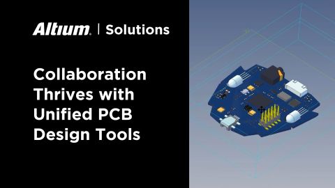
They usually have a vision they need to communicate to us, and often have to work within that, not the other way around. So, that means they need to give us very clearly dimensioned drawings and models, but this works best when we can give them an idealized model of the PCB. If we’re working with the mechanical side, after we get the initial component placement done, we’ll give the mechanical engineer access to our project files so they can import it into their MCAD tool and verify everything will fit.
Warner: What trends do you see emerging that may continue to help mechanical and electrical engineers work better together now and in the future?
Peterson: As I mentioned above, electrical engineers are playing a more active role in the mechanical side, and the cloud is a big enabler of that collaboration, but you also need more than just email and chat platforms. These tools are valuable, but they don’t help you talk through the design together in real time. Anything that makes cross-collaboration easy is a big help, and I would expect to see more of that in the future.
Warner: Thanks for sharing your insights, Zach. Any last thoughts?
Peterson: Don’t be afraid to jump into a new design area and start working with new people. Continuous learning will help keep you sharp, and you’ll have fun doing it!
Note: You can read more of Zachariah Peterson’s articles on the Altium resource page and learn more about ECAD/MCAD best practices and integration on the Altium Resource page.
About Author
Related Resources
Related Technical Documentation
Design to Release, Without the Friction
- Keep reviews tied to the right version
- Reduce handoff confusion and rework
- Spot sourcing and release risk earlier
- Work solo, share when needed
Get Started
Thank you, you are now subscribed to updates.
