


Model Your PCB Supports with MCAD Integration in Altium Designer

At a Glance
You can place mechanical elements like PCB supports and mounts with the complete set of MCAD features in Altium Designer.


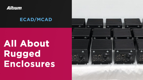
Every electronic device needs an enclosure, which means some supports will be needed for the PCB to fit and secure the PCB into its enclosure. It sounds simple, but including precise PCB supports requires careful mechanical modeling to ensure there is no interference between components and various mechanical elements. This becomes even more important when we look at flex and rigid-flex boards, which may need to move and bend during operation.
Altium Designer is the only PCB design application that helps solve this problem with a complete set of MCAD tools. Simply press a key on your keyboard, and you’ll see an ultra-accurate 3D model of your circuit board with realistic detail. You can also place your PCB supports, examine conformance to an enclosure, and export your PCB for modeling in an external MCAD application like SolidWorks. Altium Designer gives you everything you need to carefully design the mechanical aspects of your next circuit board.
ALTIUM DESIGNER®
The only PCB design application that includes MCAD features for PCB supports design, 3D component layout, and routing, and exporting to other MCAD applications.
Any new modern circuit board design contains a broad range of components, and designers need to consider how their board will mount to its enclosure or how it fits in a multi-board assembly. Components like passives and specialized ICs or SoCs are standard in most designs, but PCB supports provide the attachment to your PCB enclosure. With the right design tools, a PCB layout can be designed with more than just mounting holes.
Instead of placing simple mounting holes in a PCB layout, designers can place a range of mechanical elements like connectors, screws, bolts, guide keys, posts, and much more. Doing this correctly requires a set of MCAD features, and these same MCAD tools can be used for much more complex PCB design tasks. Here’s why your design team needs a complete set of ECAD and MCAD tools and why these tools work best when they are integrated into the same design application.
Why PCB Designers Need MCAD Features
It seems like every year, new designs become more complex and contain more features packed into a smaller space. Every new design now has very specific electrical and mechanical requirements that need to be followed, yet most designers are still forced to use different programs to confront design challenges in each area. This reduces designer productivity and creates the potential for errors as neither program can work off the same file formats or design rules.
Today’s designers need a unified ECAD and MCAD environment to help them design and place mechanical supports in their board. When designers can access these features within their PCB design software, it’s easy to prevent mechanical interferences in simple rigid boards and in complex flex, rigid-flex, and multi-board assemblies.
Design Any Complex Assembly in Altium Designer
The ECAD and MCAD tools in Altium Designer are fully integrated, meaning users can access mechanical design tools alongside industry-standard ECAD features. This is exactly what designers need to create high-quality flex, rigid-flex, and multi-board assemblies. Designers can use Altium Designer’s comprehensive ECAD toolset to create circuit board layouts, and they can define board assemblies with MCAD tools in a single application.
- Altium Designer is the only PCB design platform that allows you to take a new design from idea to complete layout and finished product in a single program.
See how you can take a design from idea to complete PCB layout in Altium Designer.
- Advanced flex and rigid-flex boards need careful mechanical design to ensure structural stability and prevent fracture. With Altium Designer, you can easily model these assemblies without using an external program.
Learn more about modeling static and dynamic flex ribbons in your PCB.
- Multiboard assemblies require the same type of MCAD tools needed to place PCB supports in a new layout. Multiboard systems also require extremely accurate MCAD modeling, and this works best in Altium Designer’s integrated set of MCAD features.
See how you can get started with multi-board PCB design in Altium Designer.

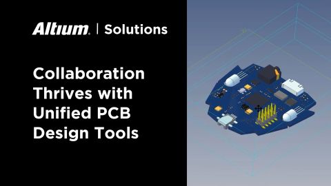
Altium Designer integrates design data across tools and management features.
Placing and Viewing PCB Supports in 3D MCAD Tools
MCAD tools work with a number of proprietary and vendor-neutral file formats, but not all ECAD applications provide this same type of support. As a PCB design application that also supports mechanical modeling, Altium Designer also allows you to import 3D models of PCB supports and place them in your layout. Popular vendor-neutral file formats are supported, and connector extensions are available for integration with popular MCAD applications. What sets Altium Designer apart is the integration of these MCAD features alongside your ECAD features, allowing you to place any PCB supports or other mechanical components into your PCB layout alongside your electrical components.
Extreme ECAD/MCAD Integration in Altium Designer
Thanks to Altium Designer’s extreme level of integration, it’s easy to place any PCB support element or other mechanical elements in a PCB layout without using a separate program. STEP models for these components can be instantly imported into Altium Designer and placed in a PCB layout by attaching these models to a mechanical component. The PCB support component can then be used in later designs as needed.
Altium Designer is one of the few design platforms that also supports a simplified integration with Solidworks. The Solidworks connector extension is available to all Altium Designer users, and this extension allows a circuit board layout or multi-board assembly to be exported for use in Solidworks. Designers can then create and model enclosures for their boards while also checking for mechanical interferences and verifying PCB supports placement.
- Altium Designer makes it so easy to add ECAD/MCAD models to your designs thanks to the Manufacturer Part Search panel. No other PCB design software application provides this type of integration with ECAD models and supply chain data in a single program.
Learn more about the Manufacturer Part Search panel in Altium Designer.
- Your PCB design rules should apply to ECAD and MCAD tasks in your PCB layout. The MCAD tools in Altium Designer can use your ECAD design rules to spot mechanical interference in 3D.
Learn more about interference checking using your PCB design rules.
- As long as MCAD models of your PCB supports can be exported into a STEP format, you can import these models into your PCB components within Altium Designer. You can then place PCB supports in your layout just like any other component.
Learn more about working with STEP files in your PCB libraries.

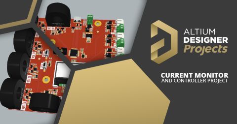
Mechanical elements like screws, testpoints, connectors, and much more can be placed in your PCB layout and viewed in 3D.
Altium Designer’s Unified Design Environment
Altium Designer provides more than MCAD tools alongside PCB layout features. Altium Designer provides everything needed to take a new design from concept to finished product, and all without needing to exit the main application. Users can access the following set of design features:
- A powerful schematic editor with a complete set CAD tools
- 2D and 3D PCB layout features that provide ultra-accurate component placement
- A simple but powerful routing engine that supports multi-Gbps signaling standards
- Pre-layout and post-layout simulation and analysis packages
- A complete set of manufacturing documentation tools and generators
- Access to a set of managed component libraries with PCB footprints and ECAD data
- And much more…
The power of Altium Designer lies in its rules-driven design engine, which automatically evaluates a layout as it’s created. This powerful engine allows every tool in Altium Designer to work off the same set of design rules and checks a design instantly during layout. PCB designers know that Altium Designer helps them stay productive.
Altium has Created a Complete PCB Design Platform
Thanks to the complete set of electrical and mechanical design tools, as well as integration with industry-standard programs like Solidworks, Altium Designer users can take a new circuit board throughout the entire design process. Every aspect of simple circuit boards, complex multi-board PCBAs, and flex/rigid-flex circuit boards can be designed with extreme accuracy. Don’t get stuck using other design platforms that don’t help you stay productive, use the complete set of world-class design tools in Altium Designer.
- The power of Altium Designer’s unified rules-driven design engine gives you a complete set of ECAD and MCAD features in a single program. You’ll have everything needed to create high-quality designs and manufacture a new circuit board with Altium Designer.
- Altium Designer’s fusion of ECAD and MCAD capabilities makes it unique among PCB design applications. Take full control over your mechanical assembly using native 3D design in Altium Designer.
- Once you’ve placed your PCB supports into your design, you can share your entire project with collaborators or your manufacturer using the Altium 365 platform. You can then easily create, share, access, and download design and sourcing data inside Altium Designer.
- Learn more about the Altium 365 platform.

Altium Designer includes everything needed for accurate ECAD and MCAD design in a single program.
While other PCB design applications separate features into multiple programs, you’ll have everything you need to create high-quality circuit boards in Altium Designer. You won’t need a separate program to design enclosures, model mechanical supports, and comprehensively inspect mechanical interference in your designs when you make the switch to Altium Designer.
Altium Designer on Altium 365 delivers unprecedented integration to the electronics industry until now relegated to the world of software development, allowing designers to work from home and reach unprecedented levels of efficiency.
We have only scratched the surface of what is possible to do with Altium Designer on Altium 365. You can check the product page for a more in-depth feature description or one of the On-Demand Webinars.

About Author
Related Resources
Related Technical Documentation
Table of Contents
Design to Release, Without the Friction
- Keep reviews tied to the right version
- Reduce handoff confusion and rework
- Spot sourcing and release risk earlier
- Work solo, share when needed
Get Started
Thank you, you are now subscribed to updates.
