





What Makes a Product Ready for Mass Manufacturing? What Design and Supply Chain Teams Need to Know

At a Glance
This article explores the essential criteria that determine whether a product is truly ready for mass manufacturing. It emphasizes that readiness hinges on the interplay between design maturity and supply chain capabilities, moving beyond the simple question of functionality to whether a product can be produced at scale while maintaining quality, cost, and schedule.


Mass manufacturing readiness now sits at the intersection of product design, production engineering, component supply, test strategy, supplier capability, and release discipline. The most important shift is that teams are no longer asking only whether a product works but whether it can be built repeatedly and scaled without losing control of quality, cost, or schedule.
This article explains how a product transitions from prototype to mass manufacturing, why readiness depends on both design maturity and supply chain maturity, and how digital engineering platforms help turn a working design into a controlled production system.
Key Takeaways
- A product is ready for mass manufacturing when it can be built repeatedly, tested efficiently, sourced reliably, and released under control.
- Prototype success proves technical possibility. Mass manufacturing readiness proves repeatability at scale.
- Products made ready for mass manufacturing must also have a supply chain secured for the product, with contingencies that can help get the product through its lifecycle.
A working prototype can be misleading. It proves that a product can function once, under controlled conditions, with engineering support close at hand. Mass manufacturing asks a much harder question: can the product be built hundreds, thousands, or millions of times with stable yield, controlled cost, approved suppliers, clear documentation, and repeatable test results?
That is where many product teams discover the real gap between design success and production readiness. A PCB may pass bench testing but still fail design-for-manufacturing review. A bill of materials may support prototypes but collapse under volume demand. A mechanical tolerance may work in a lab build but create assembly variation on a production line. A supplier may have samples available but no credible path to long-term allocation, compliance, or second sourcing.
In plain English, mass manufacturing readiness is the point where the product is no longer dependent on heroic engineering effort, but it has become a stable, repeatable, and suppliable system.
Why Prototype Success Is Not Manufacturing Readiness
The biggest misconception in hardware development is that a successful prototype means the product is nearly ready for volume. It does not.
A prototype is often built with flexible methods, close engineering supervision, manual rework, expensive parts, and without expectations on yield. Mass manufacturing is different. It depends on achieving high yield in a repeatable process, which requires monitoring quality and processing parameters throughout the production process.
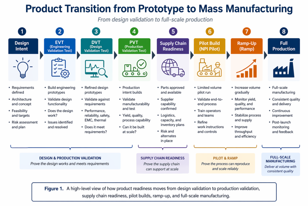
Design for manufacturing, or DFM, is the discipline that closes this gap by reviewing a product to optimize dimensions, materials, tolerances, and functionality for efficient manufacturing. In PCB development, DFM and DFA are framed as design requirements that ensure a board can be fabricated and assembled using real manufacturing technologies and production-aligned constraints.
That means the design team must ask production questions before production begins:
- Can the PCB be fabricated with standard processes?
- Can the assembly house place the components reliably?
- Are test points accessible?
- Can the product be assembled without special handling?
- Are the requested tolerances realistic?
- Can the product be repaired, inspected, labelled, packaged, and shipped without guesswork?
A prototype answers, “Can it work?” Manufacturing readiness answers, “Can it work repeatedly at cost, at quality, and at volume?”
A product ready for mass manufacturing is best understood as a layered stack. Each layer matters, but the real risk often sits between layers.
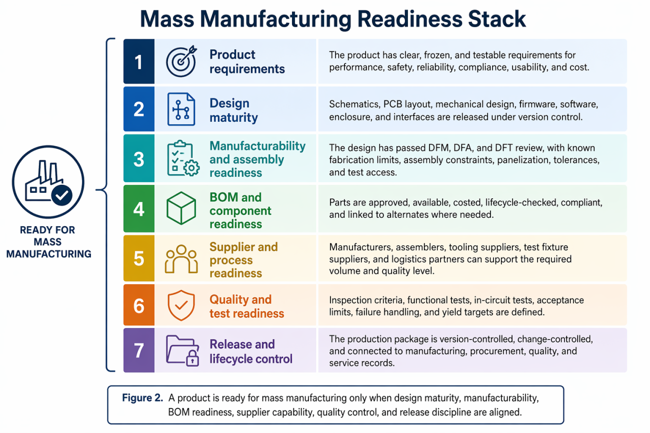
DFM, DFA, and DFT Are Not Optional
The transition to mass manufacturing depends heavily on three design disciplines: Design for Manufacturing, Design for Assembly, and Design for Testability.
DFM asks whether the product can be fabricated reliably. In PCB design, that includes material selection, board thickness, layer stack-up, trace and spacing rules, drill sizes, annular rings, solder mask constraints, copper balance, controlled impedance, panelization, and fabrication tolerances.
DFA asks whether the product can be assembled efficiently. That includes component placement, orientation, spacing, pick-and-place compatibility, soldering method, connector access, enclosure fit, cable routing, fastening sequence, and ergonomic handling.
DFT asks whether the product can be tested effectively. That includes test points, boundary scan, in-circuit testing, functional test coverage, fixture access, programming access, calibration, failure diagnosis, and production test cycle time.
IPC has developed DFM profiles based on electronics standards and performance classes to help designers check requirements across different product types, from simpler electronics to human-life-critical electronics. These profiles draw on standards such as IPC-2221, IPC-2222, IPC-7351, IPC-J-STD-001, and related documents.
A product can pass a design rule check and still be expensive or unstable to manufacture. A PCB can be electrically correct but difficult to assemble. A device can function perfectly but be slow to test. Each of those issues becomes more expensive at scale.
The Supply Chain View: A BOM Is Not a Supply Chain
From the supply chain perspective, manufacturing readiness starts with the bill of materials, but it does not end there. A BOM may be technically correct but commercially fragile. It may include parts that are available in small quantities but constrained at volume. It may rely on a single-source component.
A prototype BOM often reflects what engineers could buy quickly at low quantity, usually from a distributor like Mouser or Digi-Key. A production BOM must reflect what the business can source repeatedly, which often means signing an LOI with a volume distributor or directly with the component manufacturer.
Component evaluation is a core part of manufacturing readiness because contract manufacturers and engineering teams need to identify parts that are end-of-life, long lead time, unavailable, non-compliant, or difficult to substitute. DFM and NPI guidance commonly treats BOM review and component availability as early readiness checks, not late procurement tasks.
Design Readiness vs Supply Chain Readiness
A product becomes ready for mass manufacturing when design readiness and supply chain readiness converge.
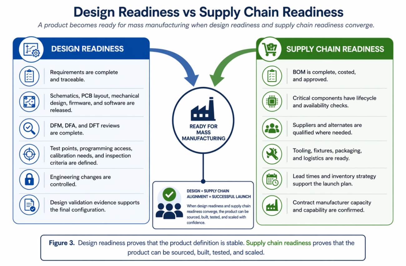
This is where launch teams often get into trouble. Design teams may assume procurement can solve component risk later. Procurement may assume engineering can approve substitutes quickly. Manufacturing may assume design intent is already frozen. Quality may assume test coverage is already built into the product.
Mass manufacturing readiness requires those assumptions to be replaced with evidence.
EVT, DVT, PVT, and the Path to Scale
A useful way to think about the transition is through validation builds.
EVT, or Engineering Validation Test, asks whether the core design works. This stage is about technical feasibility, early prototypes, engineering debugging, and major design learning.
DVT, or Design Validation Test, asks whether the design meets requirements. This stage is about validating the near-final product against performance, reliability, regulatory, environmental, usability, and design requirements.
PVT, or Production Validation Test, asks whether the manufacturing process can build the product. This stage is about pilot production, production tooling, production fixtures, operator instructions, yield, cycle time, process capability, and quality controls.
The common flow is Concept → Feasibility → EVT → DVT → PVT → Mass Production, with each stage answering a different readiness question. Tulip similarly describes NPI as moving through planning, design and development, prototyping and testing, pre-production, production ramp-up, and full-scale production and launch.
The key lesson is that mass production should not be the first time the full system is tested. By the time a product reaches volume, the team should already have proven the design, the process, the supply chain, the test method, and the release package through controlled builds.
Where the Real Manufacturing Risks Sit
Teams tend to focus on the headline items: the processor, display, battery, enclosure, or main sensor. But manufacturing problems often emerge from smaller details: component footprints, solder paste apertures, connector access, adhesive cure time, cable routing, screw torque, label placement, programming time, test fixture wear, packaging damage, or a missing alternate supplier.
In electronics, DFM and DFA requirements specifically force teams to consider whether the PCB can be manufactured, whether it can be assembled through automated processes, whether manual steps increase cost, and whether stock issues exist. Prototype readiness guidance also emphasizes that fabrication data, revision identity, stack-up intent, BOM identity, and test expectations need to travel together before a first-build or production decision is made.
What Teams Need to Ask Before Mass Manufacturing
A product is not ready for mass manufacturing until the team can answer a practical set of questions.
- Is the product configuration frozen and clearly released?
- Have DFM, DFA, and DFT reviews been completed?
- Are fabrication, assembly, test, and inspection requirements clear?
- Is the BOM complete, approved, costed, and checked for availability?
- Are critical parts supported by alternates or risk mitigation plans?
- Has the production process been validated through pilot builds?
- Are tooling, fixtures, programming stations, and test equipment ready?
- Are work instructions, quality criteria, and failure-handling processes defined?
- Can suppliers support the planned volume, lead time, and quality level?
- Is there a controlled process for engineering changes after release?
The most resilient teams can answer these questions before the ramp begins, not during the ramp.
A More Useful Way to Think About Manufacturing Readiness
The broader lesson is that mass manufacturing readiness is not a finish line after design. It is the point where design intent, production capability, supply chain reality, and quality evidence converge.
A product that works is not automatically ready to scale. A BOM that can be purchased once is not automatically ready for production. A manufacturing partner that can build a pilot batch is not automatically ready for full-rate production. A release package that makes sense to the design team is not automatically clear to the factory.
The gap between a working prototype and a production-ready product is rarely a design problem alone; it is a collaboration problem. Design, procurement, manufacturing, and quality teams each hold a piece of the readiness picture, and when those pieces live in separate tools, emails, and spreadsheets, the gaps between them become the source of late-stage surprises.
Altium Agile Teams gives multidisciplinary electronics teams the shared visibility, structured workflows, and repeatable processes they need to close that gap earlier. From real-time BOM management with live supply chain data to managed design reviews with structured sign-offs, it brings the structure that manufacturing readiness depends on into the design environment itself so teams arrive at production with evidence, not assumptions.

About Author
Related Resources
Related Technical Documentation
Table of Contents
- Key Takeaways
- Why Prototype Success Is Not Manufacturing Readiness
- DFM, DFA, and DFT Are Not Optional
- The Supply Chain View: A BOM Is Not a Supply Chain
- Design Readiness vs Supply Chain Readiness
- EVT, DVT, PVT, and the Path to Scale
- Where the Real Manufacturing Risks Sit
- What Teams Need to Ask Before Mass Manufacturing
- A More Useful Way to Think About Manufacturing Readiness
Speed at Scale. Structured Repeatability. Secure Flexibility.
- Start up fast with out‑of‑the‑box workflows
- Collaborate using ECAD‑MCAD codesign tools
- Manage BOMs with live supply chain part data
- Manage access and security as teams scale
Contact Us
Thank you, you are now subscribed to updates.