


Multilayer PCB Design: Manufacturing Boards for High Voltage PCBs
One of my favorite movies is the original Shrek. It was thrown into the nerd vernacular of my friends and siblings, along with more traditional sources of quotes, like Star Wars. One scene particularly stands out, when Shrek explains to Donkey that ogres, like himself, are complex creatures. “Onions have layers. Ogres have layers. Onions have layers. You get it? We both have layers.” Donkey points out that not everyone likes onions, but everyone likes parfait. Multilayer PCB vs single layer PCB designs can actually relate to good ol' Donkey! During a PCB design lab, a friend of mine pointed out that a multilayer PCB design falls somewhere in between parfait and onions, on the spectrum of how much one might like layered things.
Given the complexity of a multilayer PCB design, I often find them closer to onions than parfait. One thing that helps me to like them better is understanding how they are manufactured, and how my design is affected by that process. It’s even more important to understand manufacturing impacts if you have a high voltage design.
How is a multilayer PCB manufactured?
When you send your PCB designs to a manufacturer, they produce a multitude of separate layers that eventually come together into your finished circuit board. The copper traces are imaged and etched, then laminated. These layers are squeezed together with insulating material by incredibly powerful hydraulic presses, then the top and bottom layers of the circuit board are processed.
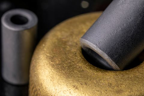
The inner layers of the board are made from “prepreg” (shortened from pre-impregnated), which is fiberglass impregnated with resin. The percentage of resin in the prepreg affects how the board squishes together in the hydraulic press. You want to optimize the amount of prepreg and the viscosity based on your final application, and to avoid any failures during manufacturing.
If the percentage of glue in the prepreg is too high, it will squeeze out between the layers. While this might make for a delicious frosting scenario, it is just as messy and bad for manufacturing PCBs as you can imagine. Too much prepreg, and the board is too thick, which invalidates all your voltage protection calculations.
What is resin?
For a standard PCB, manufacturers would probably use a low cost, high volume prepreg material that has a low resin and high glass content (glass affects the resin penetration). For high voltage applications, you want a prepreg that has a high resin percentage so there are no voids remaining after the layers are pressed together. Those voids change the effective dielectric of your insulator layers and are another way to invalidate all your voltage protection planning.
Specialty high voltage prepregs like 1080 or 2113 are a good choice here. They have a higher resin percentage and thinner layers to keep any voids or micro bubbles from being trapped, which improves the density of all those layers. In our theme of layered foods, a flaky, baklava style layering is really bad for high voltage performance. These prepregs also have smaller glass styles, so the resin penetrates better. They are much more expensive but provide comparably improved protection for high voltage.
How thick are the layers of a multilayer PCB board?
One layer of a typical prepreg multilayer printed circuit board is usually ~0.002” (0.05 mm) thick. It’s possible to get your prepreg layers made with a custom thickness, but this costs more and rarely gives many advantages in the final board performance. However, like anything manufactured, the prepreg specs come with a tolerance. Ask your manufacturer what the tolerance is for the prepreg they will be using.
A small percentage error on half a millimeter doesn’t seem like much. When you start putting dozens of layers together, it adds up and can start to affect your final specifications. In general, the tolerance on prepreg tends towards the thicker side, rather than a mix of thick and thin that averages out at the end.
What happens after the circuit board layers are pressed?
After the all the layers of prepreg and copper have survived the hydraulic press, the finished boards are baked. Alas, this doesn’t take us back to our dessert theme. The boards are baked for about 20 hours at 260F for a final outgassing. This dries any moisture remaining in the resin and removes volatiles, hopefully eliminating any micro bubbles left in the layers.
If the final printed circuit board application is in a vacuum, or a low-pressure environment, the boards get additional finishing. This usually consists of a second bake at a higher temperature for four to six hours and provides a final outgassing before the board goes into use.
Since there are so many variables that can affect your board, it’s good practice to start talking to your manufacturer early in the design process. Make sure they can use the prepreg style you want and produce an appropriately thick circuit board. That way you can confirm your design rules with them before you lock yourself into design choices.
Setting design rules, like layer thickness, at the beginning of your design process makes it much easier to catch errors as you work. Some EDA software require you to run a script to check, and then rework any issues. Others, like Altium Designer®, can catch problems as you work and notify you, reducing the redesign of any work you might have done before checking again.
If you have questions about how to use Altium Designer to improve your design and manufacturing process, they have representatives standing by to help.
Related Resources
Related Technical Documentation
Table of Contents
Altium is transforming the electronics industry so thoroughly that our web pages need a minute to catch up. For a short time, some information on this page may be outdated.
We appreciate your patience. It will be worth the wait!
Learn More
Thank you, you are now subscribed to updates.


