


Three Frequency Ranges For Ferrite Bead Usage

At a Glance
Three operational scenarios illustrate the three important frequency ranges for ferrite bead impedance, as well as how they affect noise in digital systems.


Of all the components used in electronics, there's one type of component that generates more controversy and misunderstanding than any other. That component is a ferrite bead. These deceptively simple components are billed as a cure-all for EMI, as a component for isolating power rails, and as a component for reconnecting disconnected grounds. Amazing that one little magnetic component can do so much!
I'm being sarcastic, obviously, because the truth is that ferrite beads are only good for those things some of the time, especially when applied in a power supply or directly on component power pins in high-speed PCBs. When dealing with this group of applications, there are three major areas where the ferrites might be applied.
- On power supply outputs pins
- In series with the VDD pins on digital ICs
- Between two power rails supplied by the same regulator
These are the three most common usages of ferrites in power circuits and on loads. What is interesting about this is that it reflects the behavior of ferrites in three possible frequency ranges: DC (or near DC), mid-range frequencies that approach the ferrite’s resonance, and very high frequencies at or beyond the ferrite’s resonance.
It's All About Power Supply Output Impedance
The usage of ferrites in the above three situations may not have an obvious relation to power-supply output impedance, but this is exactly what placement of the ferrite can modify when used as described above.
In general, it is preferred that the output impedance of a power supply be as low as possible so that no power is lost as it is supplied from the internal regulation circuitry to the output port. When a power supply needs to provide power to a digital IC with fast switching I/Os, the power supply needs to maintain low impedance up to as high frequencies as possible. This low impedance needs to extend into the high MHz range to ensure power integrity.
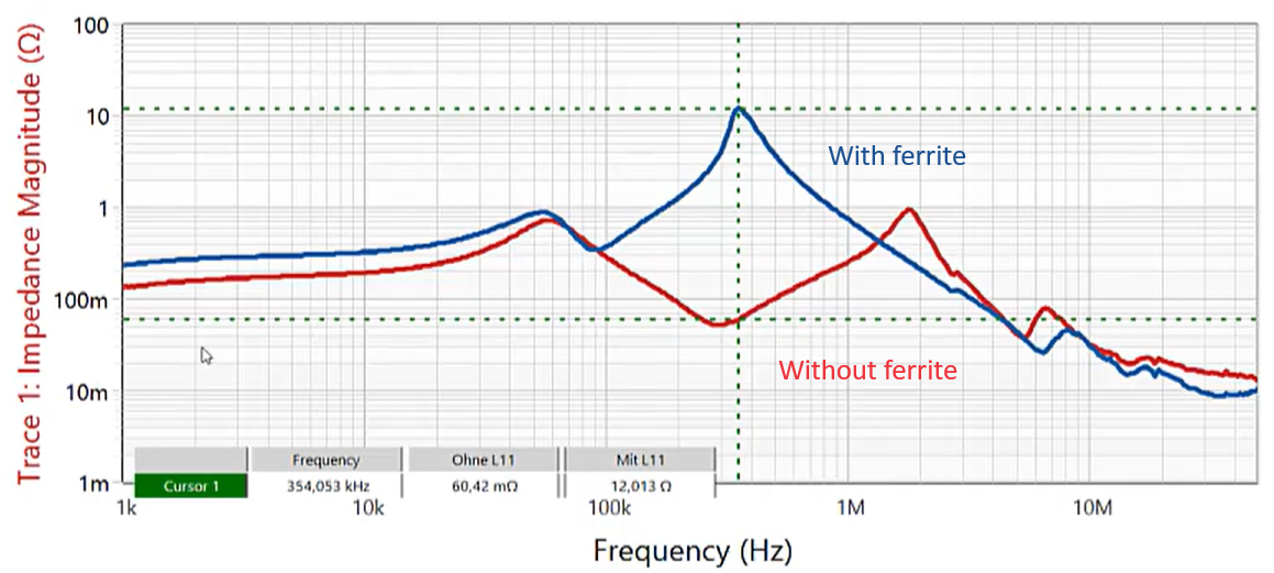
Placement of a ferrite on the output from a power supply circuit for purposes of filtering will significantly increase the power supply output impedance near the ferrite resonance, as shown in the curves below. To learn more about this, watch this presentation from OMICRON Lab on power supply output impedance.
In the above image, the blue curve shows the output impedance from a power supply with the ferrite present on the output. While it is true that the ferrite filters high-frequency noise that might conduct through the output of the power supply circuit, it also creates two problems in high-speed systems and RF systems:
- The ferrite resonates with the capacitors, leading to increased power rail noise
- The additional inductance and resistance of the ferrite can interfere with the power supply circuit’s control loop
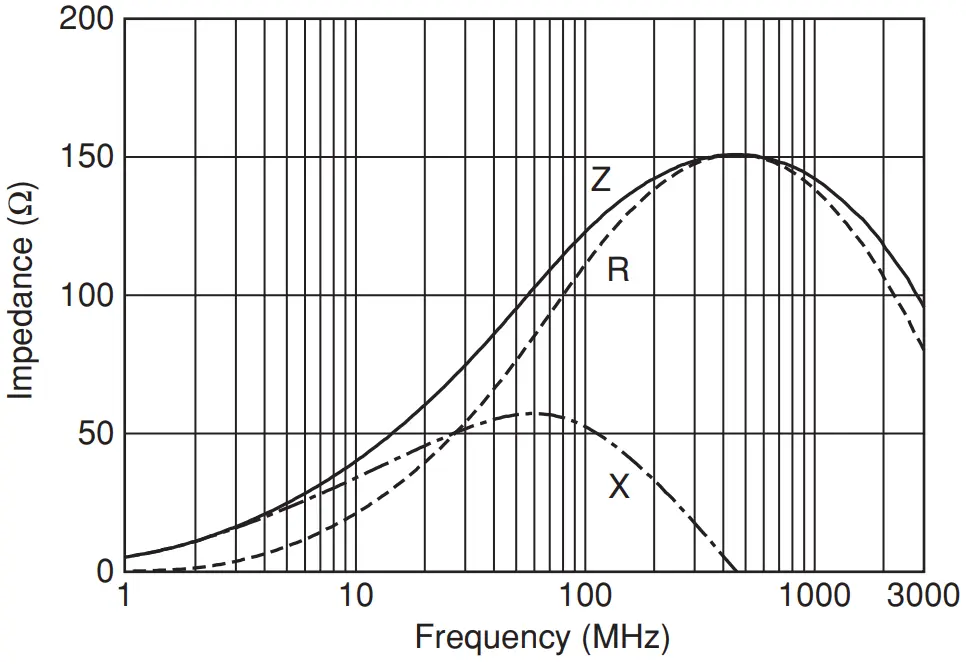
If you just look at a typical ferrite bead’s impedance curve, this should be obvious. The impedance approaches a peak in mid-range frequencies and becomes primarily resistive. What else should expect would happen when placing a ferrite on the output of a power supply?
Example ferrite bead impedance curve for part number BLM18PG121SN1 from Murata.
Now that we are armed with this information, what happens in the three situations where ferrites are placed as listed above?
Slow Response at High Frequencies
Because the ferrite becomes resistive near its resonance, it interferes with the power supply’s ability to respond quickly when a load demands power with a very fast edge rate. We can infer this just by looking at the power supply output impedance; when the output impedance is high, it is difficult for the power supply to respond in that frequency range. This will lead to larger voltage fluctuations when transients are excited on the PDN for a digital component.
However, this behavior is exactly what you would want if you are trying to filter out any high-frequency noise from the power supply. In other words, if the power supply only needs to supply DC power, and your load is always operating in DC, then the high power supply output impedance at midrange frequencies does not matter. If the load is always DC, there will never be demands for current at fast edge rates, so we don't need to worry about ripple on the PDN, and the ferrite will provide a nice filtering function.
To learn more about this, take a look at the clip from a podcast episode with Heidi Barnes of Keysight.
VDD Noise Superimposed on Output Signals
In the previous section, where a ferrite is used as a filtering component on the output of a power supply and placed onto a VDD pin, both contribute to another problem observed on the output from I/Os on a digital component. When the ferrite is put onto a VDD pin, it is now increasing the impedance of the entire PDN leading up to that pin. It’s essentially the same as increasing the power supply output impedance, and the result is the same noise in the PDN voltage.
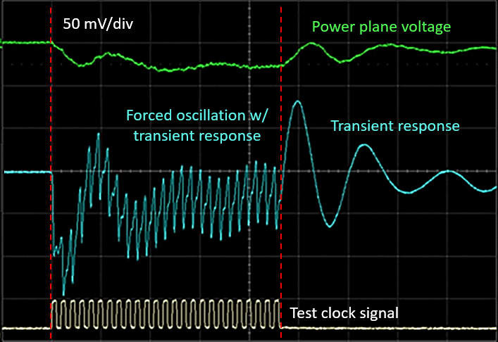
An example oscilloscope trace in the instance where the PDN has high impedance is shown below. This high impedance can come from either excess inductance or excess resistance; remember that a ferrite provides both in different frequency ranges. When the high impedance interacts with a high current, the product of the impedance and current waveform gives a voltage waveform.
Example power rail ripple measurement result for a PDN with high impedance driven with a test clock signal. Learn more in this article.
In both cases of the ferrite on the power supply output pin or the digital load’s VDD pin, the noise is then superimposed onto the voltage level for the output signals, which are directly supplied by the VDD pin. This is a prime example of a power integrity problem as observed at the VDD pin becoming a signal integrity problem, and it all originates due to a slowing down of the PDN response time when I/Os attempt to draw large currents through the VDD pin.
Isolation Between Rails
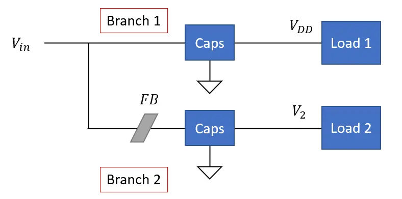
Placement of a ferrite as an isolating element between two power rails supplied by the same regulator follows the topology shown in the image below. Here, we have a single regulator powering two loads; the rails on each load are connected to each other using a single ferrite, and each rail has its own capacitance.
Topology diagram illustrating placement of ferrite bead for isolation between two loads powered by the same power supply circuit.
Placing a ferrite as an isolating element between rails has mixed results. In one sense, placing the ferrite increases the impedance along the connection, so you would expect higher noise at the isolated rail output. However, if the main rail excites a transient, you might expect that the ferrite helps filter that high-frequency noise and prevents it from reaching the isolated rail. So which of these outcomes actually occurs?
The answer is “it depends.” In particular, it depends on the following:
- The power spectrum required by the primary load
- The power spectrum required by the isolated load
- The resonant frequency of the ferrite
This should illustrate why some measurement results on this matter are contradictory; there is no hard rule as to the value of the ferrite’s resonant frequency to use in this case.
The reason for this is that the ferrite as placed in the above topology creates transfer impedance, which is a function of frequency. Therefore, there is no easy way to predict whether the ferrite is “bad” other than with an impulse response calculation, which must be done in Mathematica, Matlab, or by hand. If you’re not familiar with this, you can try with a SPICE simulation, or you can build a test board and measure it.
What Are the Frequency Ranges For Ferrites?
There is a lot of information presented above, so I think it’s important to link the ferrite placement with its appropriate operating frequency range. The table below summarizes these operating regimes where ferrites can be used and where they should not be used.
|
DC or near-DC |
|
|
Mid-range AC approaching resonance |
|
|
High-range AC above resonance |
|
I think this gives us a good rule of thumb for using ferrite beads as noise filtering elements: if your circuits intend to operate at DC or only at low frequencies, then most likely a ferrite will be just fine. If your board is using high-speed digital, even with simple SPI, you should not use the ferrite to attempt to remove noise between your power supply and your digital loads.
Whether you need to build reliable power electronics or advanced digital systems, use the complete set of PCB design features and world-class CAD tools in Altium Designer®. To implement collaboration in today’s cross-disciplinary environment, innovative companies are using the Altium 365™ platform to easily share design data and put projects into manufacturing.
We have only scratched the surface of what’s possible with Altium Designer on Altium 365. Start your free trial of Altium Designer + Altium 365 today.

About Author
Related Resources
Table of Contents
Design to Release, Without the Friction
- Keep reviews tied to the right version
- Reduce handoff confusion and rework
- Spot sourcing and release risk earlier
- Work solo, share when needed
Get Started
Thank you, you are now subscribed to updates.

