Why Are Advanced Car Radars Using So Many Antennas?

Over the past two years, I’ve worked on nearly a dozen radar modules, mostly targeting the automotive market. Closely related fields are drone radar, radar sensors for robots and industrial systems, radar vital sign sensing, motion and gesture tracking, and advanced security systems. The big fish from a business standpoint is in automotive, where more and more ADAS systems are looking for better ways to capture important data from the surrounding environment.
The operational goals in these systems boil down to building systems that can support autonomous vehicles while also making cars safer in general. However, to do this, radar systems operating at very high frequencies are following two trends:
- Newer radars are using very high antenna counts, much higher than would be used in a typical car radar module (see here for an example)
- Radar data could be used alongside other sensor data to infer additional qualities of tracked objects
For anyone looking to design innovative systems in this area, it’s important to follow these PCB design guidelines to take advantage of higher antenna counts. First we’ll look at why innovative radar systems are using so many antennas in small spaces, and how the PCB needs to be structured to take advantage of these advanced capabilities.
Higher Antenna Counts Offer Imaging Capabilities
What happens when we have an RF system with multiple co-located transmit and receive antennas operating simultaneously? Radar systems are using this architecture with a high number of co-located antennas to improve their capabilities in the following areas:
- Higher antenna count = higher resolution
- Higher antenna count = higher gain = longer range
- Higher antenna count = wider scanning field of view
- Higher antenna count = MIMO functionality for tracking multiple objects
Just as an example, take a look at this recently released image of the PCB used in a Tesla radar module. The PCB shown in the image below was take from a Tesla radar as part of a teardown by Tegan Courts on Ghost Autonomy. In this image, we see a set of series-parallel patch antenna arrays, with 14 total elements and 234 radiating patches spread across the module.

The goal in designing newer radar systems with high co-located antenna counts is to implement imaging capabilities. When the angular resolution of these systems becomes high enough (less than 1 degree in each orthogonal scan direction). This would be evaluated by looking at a gain vs. azimuth (or gain vs. elevation) graph. In general, as more antennas are added to the array, the peak gain will be higher and the angular resolution around the peak will be more narrow.

A graph like that above illustrates that the radar system can provide extremely fine scans, meaning multiple radar measurements can be taken across a single object. Those scans at each angle can be used to construct 2D images.
When paired with another sensor, such as a camera, the radar imaging system can now identify and track the motion of objects with very high precision. This begs the question, why not just track objects using cameras directly, or why not use lidar?
Why Not Cameras and Lidar?
Technically, you could do this same type of scan with lidar, but a lidar system requires a more complex optical sub-system than you will find in a comparable MIMO radar system. This is why we have seen a shift from vision systems, to lidar, and now to the use of radar.
Radar systems can be used to form 5D images (x and y coordinates in the 2D image, range, heading, and speed), and a new image can be instantly generated at another time step through a repeated radar scan. With more antennas packed onto a PCB, you have continuously increasing resolution that rivals lidar.
What about cameras? Attempting to infer object identification, categorization, range, heading, and speed from a single video clip is extremely data intensive. If the number of frames required for accurate identification is proportional to N, then the amount of training data required to train on all 5 degrees of freedom is proportional to N5. It should be obvious that this is impractical, especially because radar provides direct measurements of 3 of these degrees of freedom and they don’t have to be inferred from image data.
The other reason for the high antenna count is multiple object tracking. This is another area where attempting to track range, heading, and speed from a video stream is extremely data intensive due to the training dataset requirements; it simply can’t be done with a 2D imaging system based on cameras. In contrast, radar can measure heading, range, and speed directly without AI.
Radar systems with high antenna count can implement MIMO functionality across the array, which allows multiple objects to be identified and tracked through direct measurement, meaning no AI inference is needed for the first step. Once an object is identified, the radar can perform a high-resolution scan of the object for identification/categorization as a still image with a basic neural network for standard computer vision.
How Large Are These Arrays?
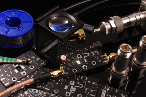
The type of angular resolution graph could be produced with a virtual array with ~100 or more antennas; for example, this could be reached with a 10 x 10 Tx/Rx array of patch antennas on a single PCB. These patch antenna arrays look similar to the image below, where a high number of emitters are placed on the same layer.

Based on the AI inference needs in advanced radar systems outlined above, and the elimination of complex optical systems in lidar or intensive training requirements in video systems, it should be clear why high-resolution radars with high antenna counts are advantageous. If you want to build one of these systems for robotics, drones, vehicles, or any other system that benefits from object tracking, then some standard PCB design rules will apply. Take a look at the following resources to learn more about placement and routing of large arrays:
- What is Hybrid Beamforming?
- How to Design a Hybrid PCB Stackup
- RF PCB Material Comparison for mmWave Devices
- Phased Array Antenna Design for 5G Applications
Beyond Car Radar?
As I mentioned above, there are other important areas where radar systems with high antenna count are applicable. These systems require integration with other sensing systems, including cameras and microphones, in order to have greater perception of the surrounding world. The next robotics system that has motion tracking capabilities and gesture recognition will do so with radar, which is much easier today thanks to many integrated circuit options for radar transceivers.
Whenever you want to build cutting-edge RF systems, use the complete set of PCB design features and world-class CAD tools in Altium Designer®. To implement collaboration in today’s cross-disciplinary environment, innovative companies are using the Altium 365™ platform to easily share design data and put projects into manufacturing.
We have only scratched the surface of what’s possible with Altium Designer on Altium 365. Start your free trial of Altium Designer + Altium 365 today.

About Author
Related Resources


Related Technical Documentation


Table of Contents
Take advantage of the world's
most trusted PCB design system.
One interface. One data
model. Endless possibilities.
Effortlessly collaborate with
mechanical designers.
The world's most trusted
PCB design platform
Best in class interactive
routing
View License Options
Thank you, you are now subscribed to updates.