


DbLibs and Electronic Components in the Cloud with Altium 365

At a Glance
Industry expert Davide Bortolami discusses what DbLibs are, how they work, what they can help you achieve, and how to integrate them with Altium 365. Spoiler alert: it’s disgustingly easy.


Altium’s DbLib support is one of the oldest and most loved features of Altium Designer for managing electronic components and their data. They’ve been present in the software world since before I could fathom the existence of Ohm’s law. Now with Altium 365 being the new mode of creating and managing projects, design teams have a secure cloud environment they can use to host and share their projects, libraries, component data, and manufacturing data.
For component data, Altium Designer 20.1 included a new Component Sync feature that allows you to synchronize virtually any database or database Library with Altium 365. The same ideas presented here also apply in Concord Pro for on-premises deployments in a secure environment. We will discuss what DbLibs are, how they work, what they can help you achieve, and how to integrate them with Altium 365. Spoiler alert: it’s disgustingly easy. This guide is suitable for both experienced and novice DbLibs users, and together with Altium’s documentation, contains everything you need for successful integration. We will fly over all past approaches that are no longer relevant, first diving into the newer techniques only.
Understanding DbLibs and DbLink
If you’re not familiar with DbLibs, this will serve as a quick introduction.
Altium Designer supports numerous file-based library formats: PcbLib, SchLib, LibPkg, IntLibs; PcbLibs contain the footprint, SchLibs contain the schematic symbol and link to the footprint inside a PcbLib, and IntLibs and LibPkg allow users to consolidate multiple libraries.
Assuming the average Altium user is familiar with the aforementioned kinds of libraries, we can dive a little bit deeper into their data structure using a relational database analogy.
We can imagine the SchLib like a database table, analogous to an Excel spreadsheet. Each row of the table is one component, identified by its name. Such a table would have many columns: one for the schematic drawing; one for the “Comments” field; one for the designator; one for every parameter of our electronic components, such as “Voltage” or “Temperature”.
A PcbLib under the same analogy would be a similar but simplified table, containing only a “Name” column, a description, our footprint drawing, and not much more.
The SchLib would also need to point to the PcbLib. These are usually called links or Foreign Keys in relational databases, but if you’re not familiar with the somewhat overbearing terminology, you can think of them as hyperlinks you click on which open the right footprint for you.
Additional columns we could consider adding are for documents such as datasheets, application notes, RoHS compliance statements, and simulation data to use with Altium’s integrated, Mixed Simulation environment.
To complete our analogy, LibPkg would be a list of all our tables (or Excel spreadsheets), and IntLibs would be a zipped export of our database ready to be shared with anyone who needs it.
DbLibs are a feature that brings this mental concept to reality, allowing you to connect Altium Designer to any ODBC-compatible database.
Altium will read one or more database tables, each of them working as a separate SchLib file. Every row in your tables will become a component in your DbLib. Several standard columns are used to define the basic component parameters and point Altium to the right SchLib and PcbLib files, usually with only one schematic symbol or PCB footprint.
DbLink works similarly to DbLibs, but without an included schematic symbol and PCB footprint, relying instead on an external file-based library and limiting itself to synchronizing parameters with existing electronic components.
DbLibs are astonishing in their flexibility. So it’s no wonder competing software houses charge exorbitant prices to enable similar features, as they allow deep integration of component libraries into existing enterprise systems.
While Altium only supports one fixed-structure table, there is no limitation on how that table may be created. Any modern relational database allows you to create database views. Views are virtual tables created dynamically and automatically by the database, following instructions written in SQL language.
The most typical example of a database view is joining together two different tables. For example, assuming we have table A containing standard DbLibs and table B containing external documentation for our electronic components, we can join them by creating a view with a query similar to the following:
SELECT * FROM A LEFT JOIN B WHERE “Part ID” = “Part ID”
Through what is called ETL (Extract, Transform, Load) processes, it’s possible to connect any software to Altium Designer’s libraries through DbLibs.
Countless companies offer ETL software and services, and often, much of the work can be achieved with just a few lines of Python.
Example Implementation: Connecting to Internal Warehouse Information
If you work in a structured company, your R&D department may run a small warehouse of sample electronic components, with each component having a shelf and box number.
Small warehouses are likely to be managed by similarly lightweight software, such as an Excel spreadsheet, Microsoft Access, or open-source software such as PartKeepr.
Integrating Altium DbLibs with your R&D warehouse can speed up your development considerably. Want to check if the component you just added to your board is the one you think, or rapidly check a connector size? Just double-click and read the relevant parameters. Similarly, such integration allows one to list electronic components shelves, and boxes directly in the BOM and print them to paper with a single click from an Altium OutJob file.
Example Implementation: Sync Manufacturer Data
Some of the most critical parameters you may wish to edit outside of the Altium Designer environment are the manufacturer and manufacturer part numbers for each component.
Passive electronic components, for example, sometimes need to be updated quite frequently: you may want to add different part numbers for 10uF 16V 0603 capacitors depending on the market fluctuation, what country your product is manufactured in, and its EMS connections. Altium’s native features and Octopart integration can significantly help the engineer to select these electronic components quickly, but in some companies, the process must inevitably go through specialized departments.
Defense and aeronautics enterprises may be required to work behind a firewall with no internet access to avoid data leaks, and thus need to replace Altium’s Octopart integration with an ad-hoc solution.
In these cases, it may be advantageous to edit Manufacturer and Manufacturer Part Number parameters outside of Altium Designer, while still leveraging Active BOM, Draftsman, and Altium’s Excel templating capabilities to generate detailed BOMs.
Example Implementation: Keep Track of P&P Data
Many companies run internal Pick & Place lines for both production and prototyping.
P&Ps are heavy cartesian machines: they pick a component in a certain point, based on an XY offset and a rotation, and move it to another, based as well on similar XY offsets and rotations.
Some of these parameters change with different boards; the most notorious example being the component center in relation to the board origin, constituting the P&P you must supply to your EMS. Other values only change with the specific part number, for example, the distance between parts in a reel or the default rotation of the electronic components.
Many P&P lines run their own management software to keep a database of all electronic components and simplify operations. To reduce the time-to-market, many companies start the setup of these parameters when the PCB design is still in progress. To this end, a pick and place management software can be integrated with Altium DbLibs and used across all of Altium’s environments.
All these values can be exported to any Altium feature that supports electronic components parameters, such as Altium Active BOM, ODB++ exports, or Draftsman tables.
Example Implementation: Connecting to Your Company ERP
When I used to work in a leading manufacturer of power inverters for water pumps, the company ran, like many others, on a custom-developed ERP software. The software survived countless updates over many decades, and while it was not the prettiest piece of digital architecture, he got the job done every time.
To integrate Altium Designer with this software, we added an SKU parameter to our pre-existing libraries. Each SKU (Stock Keeping Unit), pointed to a “product” inside the ERP software.
The ERP contained datasheets for tens of thousands of electronic components, and contextual data such as RoHS approval reports. Among the data were confidential documents that could not be transferred outside the ERP to avoid data leaks.
The ERP exported the data to Microsoft SQL Server tables, and a couple of views were created to display formatted document links solely by naming the columns following the patterns “ComponentLink1Description” and “ComponentLink1URL”. Similarly, we decided to write the component descriptions directly inside the ERP software as our purchasing department had kept the most meticulous and coherent records I had ever seen and would have continued to do so for the foreseeable future.
DbLibs and Past Limitations of Altium 365
Up to Altium’s version 20.0, when using Altium 365 in conjunction with DbLibs, it was not possible to take full advantage of all collaboration features except when confined on-premises. This is fine for secure, on-campus collaboration and parts management, but full collaboration with outside designers and stakeholders used outdated file exchange processes.
Altium 365 allows always-up-to-date and flawlessly standardized component data to be adopted in your organization by allowing every engineer to work from the same single shared library. One or more librarians can draw and validate schematic symbols, component footprints, and component parameters while the whole team can petition them to create new electronic components through Altium’s part request form.
In Altium 365, component changes are managed through a Part Lifecycle, and their adoption is also tracked in your projects through the Where Used feature. These features allow us to quickly uncover and update all designs when a component becomes inevitably obsolete, a task that in a less centralized environment can often take days of work.
All of these features, and more, were partially compromised when adopting DbLibs. DbLibs connects to databases separate from the one used by Altium 365 behind the scenes; the schematic symbols and PCB footprints must be shared and organized independently, and any lifecycle management will inevitably rely on external ERP software often not suited to the needs of component library management.
Over the years some users have also complained about a lack of performance when handling big libraries, with the primary workaround being multiple separate tables inside the DbLib. In contrast, Altium 365 is able to handle virtually limitless libraries as all search queries run on the server side, and the components are loaded dynamically in small batches when you scroll inside the Components Panel.
Altium’s New DBlib to Server Component Sync Feature
Altium 20.1 release notes can be a rather long read, as they include a whopping 106 bug fixes, 13 small new features for Draftsman, and 7 performance improvements; At least 55 issues addressed originated from the community.
This article is about one feature among many: component database-to-server data synchronization.
Sounds wordy! But the juice is simple. Take the power of DbLibs, and unify it with Altium 365 cloud offering.
The feature works as follows: If you have previously migrated a DbLib to Altium 365 using the Library Migrator, the new Component Sync feature allows you to pick up the work where you left it.
You will now be able to map your DbLib columns to Altium electronic components parameters, the same way as in a DbLib, but with additional support for extended data types such as percent and units of measures (Volt, Ampere, Ohm, …). When the sync action is triggered in one of three ways that we will discuss soon, Altium compares your database with the existing components and updates them. If required, you can also choose component templates for newly created electronic components and decide what parameters will trigger a new revision. For example, you might want a change in the manufacturer part number to trigger a new revision, but the same might not be necessary when updating warehouse locations.
The second mode of operation is triggered when, instead of connecting a full DbLib, you connect a simpler database (with no schematic symbols or PCB footprints), such as a Microsoft Access database, an Excel spreadsheet, a CSV (Comma Separated Values) file, or any other data source that include an OLE DB or ODBC driver. In this mode, the Component Sync acts like the old DbLink: your electronic components will be defined by Altium Designer and stored on Altium 365, and the columns of your database will become parameters inside your components.
Existing electronic components and database rows are matched one-on-one when the value of a specified column equals a specific component parameter.
The Component Sync feature runs on your desktop, thus enabling you to sync Altium 365 to databases that are not accessible from the internet. Additionally, the data is compressed before being sent to Altium 365, so you can easily migrate vast libraries without clogging up your internet connection.
Demonstration
In this example, I have gone ahead and migrated the table containing 0603 MLCC capacitors from Mark Harris’ Celestial Database Library to Altium 365 using the Library Migrator feature.
This electronic components library contains almost 6000 capacitors, but Altium handles the stress with grace.

I have converted the database table—initially hosted on a Microsoft SQL server—to an Excel table using DBeaver, an open-source database management software. This way, the database can easily be edited for demonstration purposes.

I have created a new Component Sync config, after enabling the feature in the platform extensions page in Altium Designer.

The config reads the only sheet inside our Excel file and syncs it with the cloud. The Component Sync has been set up to match the components by a key parameter/column named PartId.
Tips: Remember to always keep the properties panel open, so you don’t miss anything that requires additional configuration when clicking around!

I have gone ahead and modified the field Description of the capacitors in our Excel file.

After triggering a manual Component synchronization, we can see the newly updated capacitor shows up in the Components and Explorer panel.


Modes of execution
You can trigger the new Component Sync feature in three different ways:
Manually
Open the CmpSync file and press on the Execute button to trigger the synchronization manually. The task will run inside your current Altium Designer instance, and you will not be able to conduct any other task while the operation is running unless you open another instance.
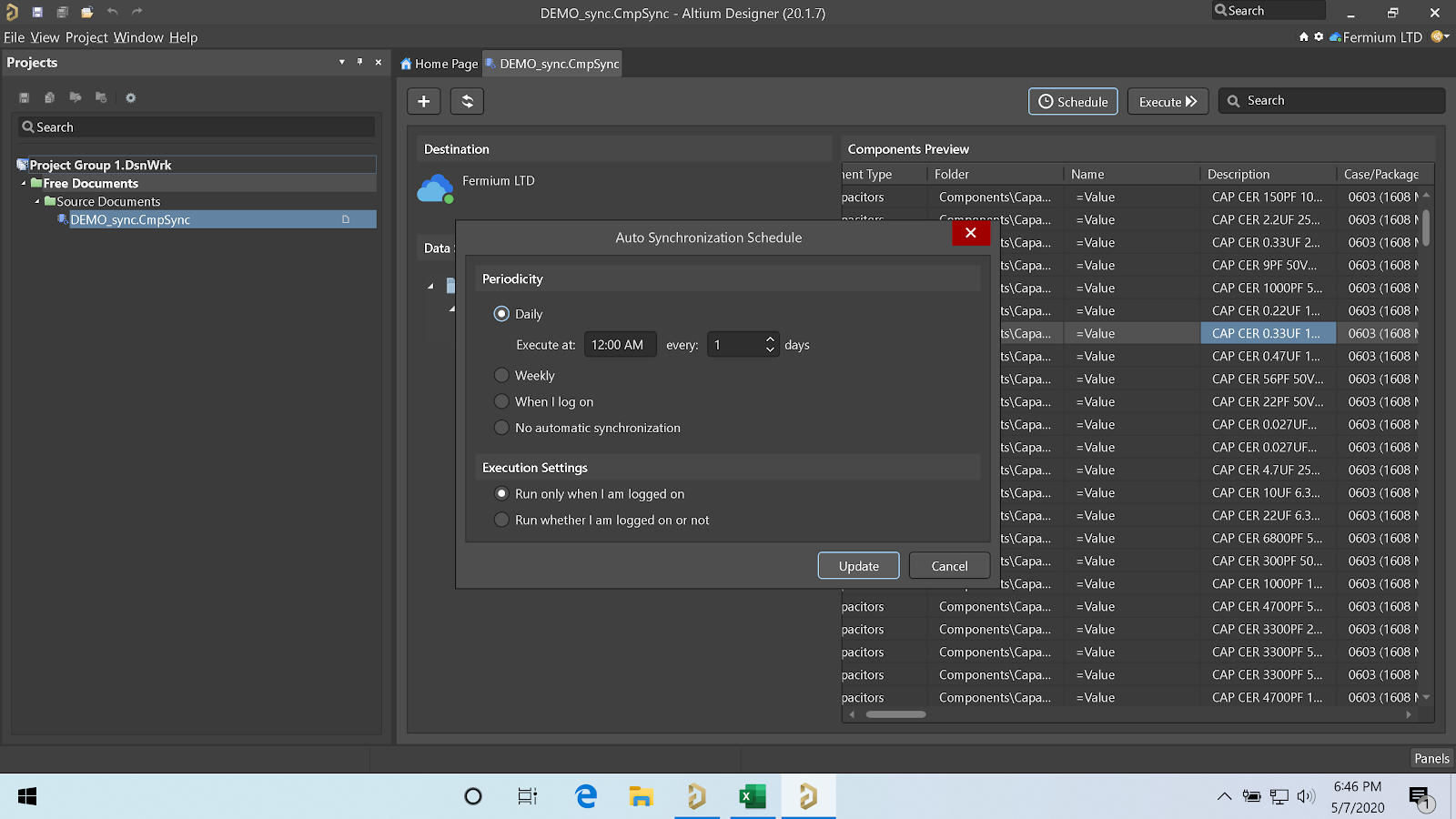
On a Schedule
By using the Schedule button, you can set a daily or weekly schedule, or trigger the synchronization when you log-in to your Altium Designer workspace.
Altium Designer will create a new Windows Schedule task.
Through the Command Line
Last but not least is the Component synchronization triggered by the command line, using the command line utility under “C:\Program Files\Altium\AD20\System\ComponentSync.Executor.exe”.
This mode is extraordinarily flexible, as it can be triggered by an external script.
For example, you might want to write a simple Python script that will query a private API exposed in your internal/external network through the following procedure:
- Connect to your REST API
- Download the data
- Write the data to a CSV file in a temporary location
- Trigger the component sync and wait for it to finish
- If completed successfully, delete the temp file and exit
- If unsuccessful, email the log file and exit
Conclusions
Altium’s DbLibs feature has always been one of the most powerful, if somewhat hidden, in Altium Designer. Understanding how to take advantage of it in the best possible way can take a lot of background knowledge in enterprise electronic components data management (and often a good session of meditation), but it can lead to astonishing improvements in efficiency and an error-rate reduction for your designs.
Up until Altium 20, it was not possible to take advantage of both Altium 365 and DbLibs at the same time without compromising on features and usability, as multiple conflicting data sources can originate confusion.
Starting from Altium 20.1, the new Component Sync feature allows merging the capabilities of database libraries with the simplicity and collaboration of Altium 365, creating a system that is far greater than the sum of its parts. Syncing electronic components' data in this way gives you a powerful set of features for management and data tracking.
Documentation on this new feature can be found here. If you want to learn the latest and greatest of automated library migration and management for your components, read this recent article.

About Author
Related Resources
Related Technical Documentation
Table of Contents
Design to Release, Without the Friction
- Keep reviews tied to the right version
- Reduce handoff confusion and rework
- Spot sourcing and release risk earlier
- Work solo, share when needed
Get Started
Thank you, you are now subscribed to updates.