


Constraint Driven Design versus Rules Driven Design in a Unified Environment


One of the most important productivity tools for PCB designers is a robust design rules checking (DRC) system or a constraints checking system. DRCs and constraints help ensure a PCB layout can comply with DFM requirements, signal integrity requirements, and custom place and route requirements that are specific to your product. Different programs display design rule definitions in different ways, design rules are defined in different interfaces, and some displays are more intuitive than others.
In the dominant CAD software packages, there are two approaches for enforcing design constraints:
- Category-based design rule definitions
- Object, net class, and layer-based design constraint definitions
Design rule definitions can be defined in either method, ultimately producing the same results. But which approach is best for your design? For some designers, it is a matter of personal preference, although some designs may be more amenable to a particular approach to handling design constraints.
Constraint-Driven Versus Rules-Driven Design
Constraint-driven design and rules-driven design both leverage an online DRC engine that allows for real-time monitoring of design constraints. Constraint-driven design and rules-driven design operate under the same basic principles: check the layout against defined design rules and display any violations to the designer. The difference between these is primarily the ease with which the appropriate design constraints can be defined in CAD, and not the way constraint violations are displayed to users.
To start, we can see some examples of PCB designs that work better with constraint-driven design versus rules-driven design. The table below provides some examples based on the design constraints which must be implemented in a given PCB project.
|
Constraint-driven |
Rules-driven |
|
|
Low net class count, but different constraints are different layers |
X |
|
|
High net class count, but constraints often the same across all layers |
X |
X |
|
Many per-net feature size and constraint definitions required |
X |
X |
|
Complex constraints requiring multiple logical conditions |
X |
|
|
Multiple mechanical constraints |
X |
|
|
Padstack/via constraints by net class or layer span |
X |
|
|
Complex priorities by layer, rooms, etc. |
X |
|
|
Fast clearance/feature size limits applied to many objects |
X |
X |
Note that the above table is based on my experience; yours may differ and you may find an approach that works well in all design categories. One should also note that there is not a requirement for either approach in a specific design; the choice to define constraints or use category-based design rules is completely up to the PCB designer.
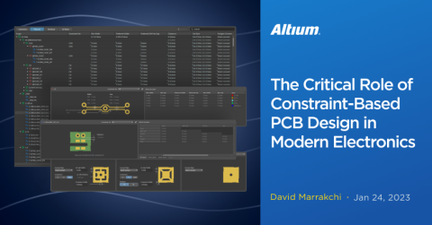
With the new Constraint Manager feature, Altium now offers the only PCB design software application that allows for either approach. Constraint-driven design or rules-based design can be selected at the outset of a project, and the appropriate design constraints can then be implemented in either approach.
Constraint-Driven Design
The Constraint Manager in Altium is similar to other PCB design software, offering a unified, table-based/spreadsheet-like editing interface for defining design constraints, which is accessible from both the schematic and PCB. Constraint management tools typically divide design constraints into three categories:
- Clearances, which define things like component placement distances and etching tolerances
- Physical, where copper feature geometries (track length, preferred vias, etc.) are defined
- Electrical, addressing constraints such as net connectivity and allowances for short circuits

One of the factors that simplifies constraint definitions which may be different in various parts of the stackup is the ability to define layer-by-layer constraints without complex queries. By default, constraints are applied to all layers, which is typical of rules-driven design. A constraint is applied to a new layer set (internal vs. external layers, for example) or to a specific layer on a cell-by-cell basis within the constraints table view. This structure makes this task of applying constraints to specific layers much simpler as the designer does not need to create complex queries or make copies of design rules for each layer.
One of the benefits of using layer definitions in a tabular view is that the constraint definions are easier to update automatically. In the rules-driven design approach, the design rules applied to specific layers often need to be updated manually if a constraint value on one layer set is changed. While this might be acceptable in a design with a small number of layer-specific constraints, larger designs with more constraints proceed smoothly as changes automatically copy themselves across layers.
Rules-Driven Design
In rules-driven design, constraints are entered individually in a larger set of categories, offering much more granular control over the physical and electrical aspects of the design. The tradeoff is that it can be more time consuming to enter a large number of constraints across multiple categories, something which might apply in a complex design. In Altium, rules-driven design is implemented by defining the following items for each rule:
- Rules scope, or which objects/locations/nets the rule applies
- Rule constraints, or the requirements imposed within the rule
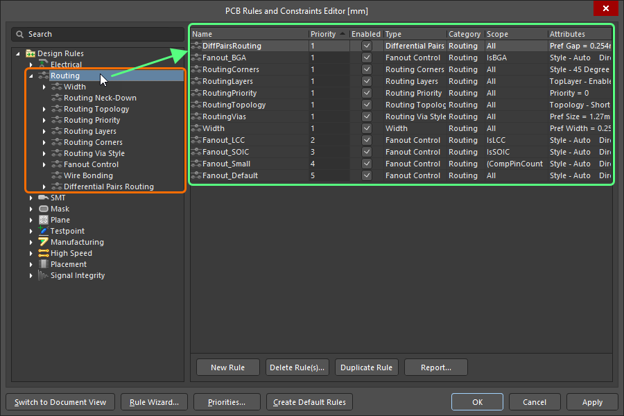
For each of these rules, the applicable scope is defined in multiple ways, such as selecting a net, net class, component, component class, footprint, or layer. In Altium, the most useful feature for customizing the scope of a rule is the ability to write custom queries for design rule scopes directly in each of the rule entries in the PCB Rules and Constraints Editor. This gives much more control over where rules apply in a design.
Which Approach Should You Use?
Both approaches are amenable to many designs, and there is an element of personal choice when defining design rules in the software. From my assessment, certain designs that require significant customization across layers and within different net classes are more easily defined in the Constraint Manager, while the PCB Rules and Constraints editor gives more granular control whenusing Rooms, defining DFM/DFA requirements, and when implementing complex queries. Try out both approaches and see what is most intuitive for your design process.
Whether you need to build reliable power electronics or advanced digital systems, use Altium’s complete set of PCB design features and world-class CAD tools. Altium provides the world’s premier electronic product development platform, complete with the industry’s best PCB design tools and cross-disciplinary collaboration features for advanced design teams. Contact an expert at Altium today!

About Author
Related Resources
Related Technical Documentation
Table of Contents
Design to Release, Without the Friction
- Keep reviews tied to the right version
- Reduce handoff confusion and rework
- Spot sourcing and release risk earlier
- Work solo, share when needed
Get Started
Thank you, you are now subscribed to updates.

