


Integrating an Electronics Enclosure Design with Altium Designer

At a Glance
Industry expert Mark Harris shows you how easy it is to create a bespoke enclosure using SolidWorks with Altium’s MCAD CoDesigner. With step-by-step guidance and seamless integration between ECAD and MCAD workspaces, you'll be able to design and update your project's electronic and mechanical aspects in parallel, ensuring compatibility and right-first-time results. Bring an end to transferring design files between teams and start a hassle-free design process!


Enclosures are a vital part of an electronic project, though until recently, designing a bespoke case was an expensive and time-consuming process. However, advances in integrating Electrical Computer-Aided Design (ECAD) and Mechanical Computer-Aided Design (MCAD) packages make this simple. We'll demonstrate how easy it is in this article, where we will integrate SolidWorks MCAD with Altium Designer, thanks to the power of Altium's MCAD CoDesigner tool.
Integrating Altium Designer With Solidworks
Altium's MCAD CoDesigner extension links directly into SolidWorks as an integrated function, operating like any of its native functions. It provides a seamless connection between the Altium Design ECAD and MCAD tools. The process is similar to most other mechanical design software, but this article will focus on integration with SolidWorks.
The CoDesigner tool provides a bidirectional communications channel between the ECAD and MCAD workspaces that automatically and invisibly transfers the enclosure design parameters. This effortless interoperability makes it easy to design and update your product's electronic and mechanical aspects in parallel while ensuring they remain compatible.
Any changes made in one workspace pass to the other, allowing the decision as to whether the changes are acceptable. Should a change in one environment cause a conflict with the design of the other, the affected design team can reject this change and pass it back for reconsideration.
Benefits of CoDesigner
This seamless design integration is the critical benefit of the ECAD/MCAD integration offered by Altium's MCAD CoDesigner tool.
This automated integration eliminates the requirement for exporting design files using intermediate formats accessible by two divergent ECAD and MCAD applications. Typically this process was time-consuming, prone to error, and challenging to coordinate and manage.
Designing an Enclosure for an Altium Design
Designing a mechanical enclosure to fit perfectly around a circuit board developed using Altium Design is quick and straightforward. We can demonstrate this by taking an electronics project created using Altium Designer, which offers realistic design challenges, to show the power of the Altium applications.
Getting Started
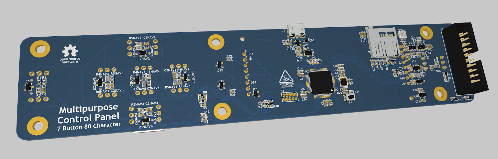
The project selected is a general-purpose control panel with an LCD, some buttons, a USB connection, and a microSD card socket. These elements will require the mechanical enclosure to have cutouts of different shapes and sizes on two surfaces. This complexity will demonstrate how simple the design process is for any enclosure type.
The control panel design we're using to demonstrate enclosure design offers several challenges thanks to its irregular shape and the different heights of the screen and buttons that will need to fit the same top surface.
While various materials and construction methods are available, the complex shaping makes 3D printing the most cost-effective method for one-off production.
Integrating the Tools
Integrating the Altium Designer ECAD and SolidWorks MCAD is simple. Just enable the CoDesigner plugin available for SolidWorks and open the CoDesigner panel in the SolidWorks application.
Importing your ECAD design file into the MCAD tool to create a new mechanical design is equally as simple. The Pull button on the Altium MCAD CoDesigner panel in SolidWorks will prompt you with a list of your Altium Design projects.
Once you've chosen a project, select where to store the new SolidWorks design file in your Altium 365 workspace.
Preparing the Board Design
The first step in creating your enclosure design around your circuit board is producing the basic structure that will form the foundation of the mechanical design. The easy way to achieve this is to add an empty component to the electronic assembly that aligns with the planes of the board.
Then, map each feature on the board requiring an opening on the enclosure surface to this assembly design. Finally, we add reference geometry to the side view of the assembly to define component elevations and clearance requirements.
The electronic design is then ready to derive the mechanical design.
Creating the Mechanical Design
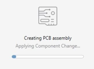
Switching from the circuit board to the enclosure document will automatically transfer all the dimensional data to create the mechanical design.
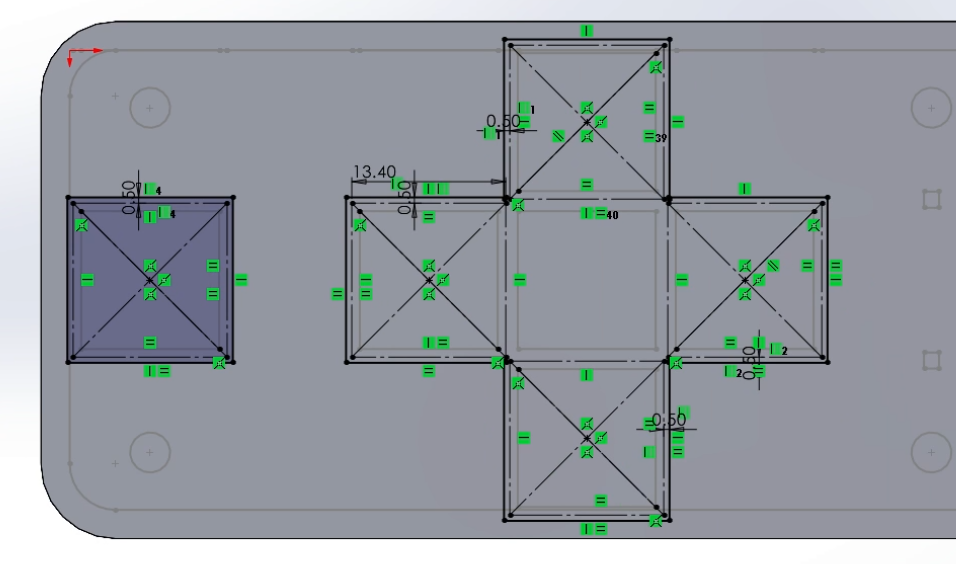
One of the challenges in this stage is ensuring that physical component and manufacturing tolerances reflect in the mechanical tolerances. An excellent example of this challenge is the through-hole-mounted switches. The inherent nature of their mounting allows movement of the switch component before soldering holds them in place. Therefore, their enclosure opening dimensions must accommodate all possible positions. We do this by adding tolerances to the dimensions of all apertures and fixing points designed into the enclosure design that must align with circuit board elements with a positional tolerance.
Similarly, the manufacturer and the manufacturing process may affect board outline tolerances.
In the example of a 3D printed enclosure, the precise nature of the manufacturing technique does not require adjustment of the circuit board design. In this demonstration, adding half a millimeter of clearance between the 3D-printed structure and the PCB features will allow for assembly tolerances for the enclosure design.
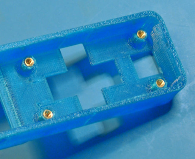
A benefit of 3D printing is that we can extrude the standoffs needed to mount the board directly into the enclosure as part of the manufacture. In this case, I've included threaded brass inserts in the standoff design to allow for repeated assembly and disassembly during development. But, of course, this addition is only necessary if you fit the board more than once.
The enclosure design also needs to include side cutouts for the USB connector and the insertion of microSD cards into its associated connector. We've designed the enclosure wall to be relatively thick to provide structural strength and stability. This allows creative design techniques to provide the required clearance for connection and disconnection and enables the inclusion of more complex and decorative elements.
Manufacturing the Enclosure
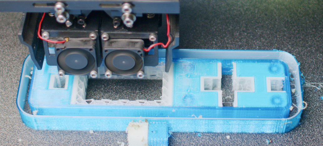
The manufacturing process employs a 3D printer with dual extruders, which allows the simultaneous printing of the enclosure structure with soluble support material.
This technique provides structural stability for overhanging and intricate parts of the enclosure during the print process. Once printing is complete, we can dissolve the support material to leave the finished enclosure.
And that's it; the bespoke enclosure designed for the circuit mount to fit perfectly within is ready to insert the threaded brass inserts and attachment of the PCB.
Conclusion
The article shows how SolidWorks integrated with Altium's MCAD CoDesigner application can make the design of an enclosure around an existing electronics project straightforward. It provides an effortless means of integrating electronic and mechanical designs to ensure right-first-time compatibility while eliminating the need for transferring design files between teams.
About Author
Table of Contents
Design to Release, Without the Friction
- Keep reviews tied to the right version
- Reduce handoff confusion and rework
- Spot sourcing and release risk earlier
- Work solo, share when needed
Get Started
Thank you, you are now subscribed to updates.


