


MCAD Collaboration in Altium Develop


Mechanical and electrical design domains share the same physical space on every product, yet they are typically developed in separate tools with separate data models. The point where these domains intersect, at the board outline, component placement, connector locations, mounting hardware, and enclosure clearances, is where costly errors accumulate if synchronization is handled poorly or too late. Late-stage discovery of enclosure interference, mounting hole misalignment, or connector-to-housing conflicts drives rework that could have been resolved during layout.
The core engineering problem is maintaining geometric and constraint consistency between the PCB layout and the mechanical enclosure model throughout the design cycle, not just at handoff. A single file export at the end of layout is not a synchronization strategy. Effective ECAD-MCAD collaboration requires a defined exchange of board geometry, component placement, keep-out regions, hole definitions, and clearance constraints, with the ability to iterate without re-creating data manually in each tool.
Data Exchanged Between ECAD and MCAD
Understanding what data actually moves between domains is the starting point for any co-design workflow. The synchronized dataset typically includes:
- Board outline and cutouts
- Component placement (X, Y, Z, rotation) with 3D body representations
- Mounting hole locations and sizes
- Keep-out and keep-in regions
- Connector and tall component positions that interact with enclosure geometry
- Copper regions (in file-based exchange scenarios)
If any of these items are modified in one domain and not propagated to the other, the result is a mismatch that may not surface until prototyping or assembly. The most common failures are connector placement that conflicts with enclosure openings, component height violations against enclosure lids, and mounting hole drift between board revisions.
While Altium Designer within Altium Develop has top-notch 3D capabilities and can generate 3D PCBs and 3D components, the reality is today’s products are defined by their enclosures or shapes, not by their PCBs. With Altium Designer’s support to import realistic accurate mechanical models, designers can work with actual product mechanical enclosures, components models, and unusual shapes that can be dimensionally critical, right into their ECAD 3D PCB editor. This helps knock down the fences that create a connection between the ECAD and MCAD design domains.
Push-Pull Synchronization vs. File-Based Exchange
There are two primary approaches to ECAD-MCAD data exchange, and the choice between them depends on the tools in use, the complexity of the product, and how frequently the mechanical and electrical designs iterate against each other.
|
Attribute |
Push-Pull Co-Design |
File-Based Exchange (IDX/STEP) |
|
Synchronization latency |
Near-real-time, per change |
Batch, per export cycle |
|
Data integrity risk |
Lower, changes are tracked and accepted/rejected per item |
Higher, manual reconciliation required |
|
Constraint coverage |
Board outline, placement, keep-outs, holes |
Geometry and copper; constraints are implicit |
|
Tool dependency |
Requires supported MCAD link (e.g., SOLIDWORKS, PTC Creo, Autodesk Fusion) |
Works with any tool that reads IDX or STEP |
|
Typical use case |
Tightly iterated electromechanical products |
Legacy workflows, unsupported MCAD tools, archival handoff |
Push-pull collaboration, where changes are proposed in one domain and accepted or rejected in the other, is the preferred method when the MCAD tool supports a direct link. This workflow allows the mechanical engineer to move a connector or adjust the board outline and push that change to the ECAD tool, where the PCB designer reviews and accepts it with full visibility into what moved and by how much. The reverse also applies: component placement changes in the layout can be pushed to the mechanical model.
File-based exchange using the IDX format (based on the ProStep EDMD standard) remains relevant when a direct link is unavailable or when copper geometry needs to be transferred. IDX carries more information than a plain STEP export, including component mapping and board region data, but it lacks the per-change granularity of a push-pull workflow. STEP export is primarily useful for transferring a 3D snapshot of the board assembly into the mechanical environment for fit checks, not for iterative co-design.
3D Model Fidelity and Format Considerations
Accurate 3D representations of components are a prerequisite for meaningful clearance analysis. If component models are simplified boxes or missing entirely, enclosure fit checks produce unreliable results. STEP is the most widely supported 3D model format for component bodies, and most MCAD tools handle it without conversion issues. Parasolid is also supported in some workflows.
The practical concern is library quality. A component library where 3D bodies are approximate or absent undermines the entire co-design workflow, because the mechanical engineer cannot trust the board assembly model for interference checking. Investing in accurate 3D models for connectors, tall electromechanical parts, and heat sinks pays off directly be eliminating enclosure redesigns.

Cross-section view showing a PCB assembly inside an enclosure.
Clearance Checking Between Domains
Clearance verification between the board assembly and the enclosure is one of the highest-value outcomes of ECAD-MCAD collaboration. In the ECAD environment, 3D clearance checking can catch component-to-component interference on the board itself. When the board model is placed inside the mechanical enclosure, the MCAD tool handles component-to-enclosure clearance, lid interference, and airflow path verification.
The gap that causes problems is when clearance rules exist in one domain but not the other. A keep-out region defined in the ECAD tool may not transfer as a constraint to the MCAD tool, meaning the mechanical engineer could place a standoff or boss in a region the PCB designer assumed was reserved. Defining which tool owns which constraints, and verifying that those constraints survive the exchange, is part of the co-design process definition that should happen before layout begins.
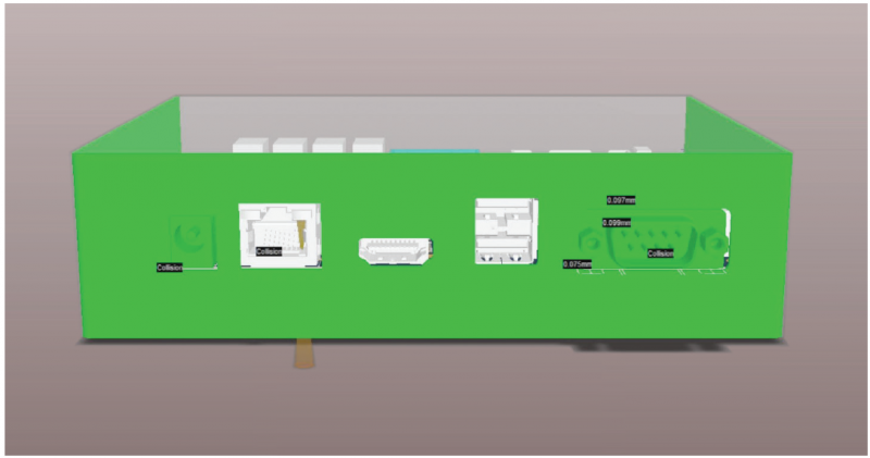
3D clearance check visualization showing can be performed as part of enclosure design in MCAD software or in the electrical space as part of component placement.
Selecting a Collaboration Workflow
The right MCAD collaboration workflow depends on the product and the team. For products with tight electromechanical integration, such as wearables, handheld instruments, or densely packaged embedded systems, push-pull co-design with a supported MCAD tool is the appropriate choice. The iteration speed and change-tracking granularity justify the setup effort.
Synchronization frequency matters as much as synchronization capability. A common mistake is treating ECAD-MCAD exchange as a milestone event, done once after placement and once before release. In practice, the following checkpoints reduce rework:
- After initial component placement, to verify enclosure fit and connector alignment
- After any board outline change, to confirm mechanical mounting compatibility
- After significant placement changes driven by routing or SI constraints
- Before design review, to ensure both domains reflect the same revision
- Before fabrication release, as a final geometric consistency check
Regardless of the method chosen, the engineering requirement is the same: geometric and constraint consistency between domains, maintained throughout the design cycle, with clear ownership of constraints and a defined process for resolving conflicts. The tooling is a means to that end.
Altium Develop supports this standard of collaboration between ECAD and MCAD domains through the MCAD Codesign plugin. This extension allows you to incrementally exchange data between Altium Designer and mechanical CAD applications (such as SOLIDWORKS) using the ProStep EDMD exchange format. Functionality includes support for change requests, as well as the transfer of Cu geometry.
Easily synchronize designs between Altium Designer and top MCAD systems. Closer collaboration between electrical and mechanical engineers opens the door to a new form of multidisciplinary electronic product co-creation. Experience Altium Develop today!

About Author
Related Resources
Related Technical Documentation
Table of Contents
Design to Release, Without the Friction
- Keep reviews tied to the right version
- Reduce handoff confusion and rework
- Spot sourcing and release risk earlier
- Work solo, share when needed
Get Started
Thank you, you are now subscribed to updates.
