What Is the Difference Between ECAD and MCAD Software?

When designing electronics, there are many tools available to make the designer's life a lot easier. Complete designs can be modeled in intricate detail in the virtual world to allow the designer to check that their design will work and that the parts will all fit together when manufactured. In the past, circuits were prototyped, and enclosures were mocked up to validate designs, but now, a computer runs these checks in seconds. With the right software, adjustments can be made quickly, simply, and with little cost. The two essential tools available to the designer are Electronic Computer-Aided Design (ECAD) and Mechanical Computer-Aided Design (MCAD) packages.
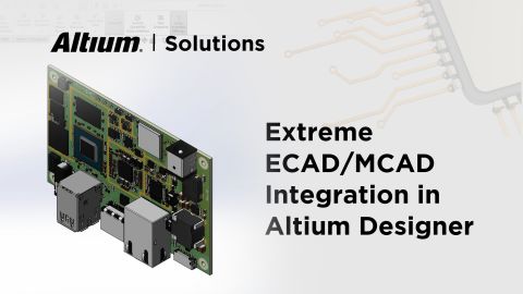
You may be wondering, what is ECAD? What are MCAD and ECAD software? But most importantly, what is the difference between them? In this blog, we're going to tackle ECAD vs. MCAD. ECAD software focuses on the electrical portion of a physical design, while MCAD focuses on the mechanical portion. Today, both sets of software come together to enable a collaborative workflow where designers in each domain can work together on a new product. ECAD/MCAD integration means an electronics design engineer can perform MCAD tasks in their PCB design software, and vice versa for a mechanical designer. Before introducing how these tools work, we should look at how each type of software works. In this blog, we're going to tackle ECAD vs MCAD.
What Does ECAD Stand For?
ECAD stands for Electronic Computer-Aided Design. ECAD software is a specialized type of CAD (Computer-Aided Design) software. It is used to design and develop electronic systems, especially printed circuit boards (PCBs). ECAD focuses on the electrical and electronic aspects of product design, while the broader term CAD can refer to any design software.
What Is ECAD?
ECAD software allows an electrical designer to create a printed circuit board (PCB) layout from a schematic of their circuit design, generate a virtual representation of their PCB showing component placement with 3D models, and generate/display 2D circuit board manufacturing documentation. Different ECAD software packages have varying capabilities, and some software forces you to use multiple programs to accomplish various design tasks.
A standardized library of component dimensions, supplemented with electrical and mechanical data for bespoke or unusual parts, provides the required board placement information defined within the physical dimensions of the PCB. Computer-assisted trace routing combined with manual and computer optimizations speeds up the layout design process. Automatic rule-checking functions can also provide a degree of assurance that the electrical layout is routed correctly before the design is put through a simulation stage. After placing the design through a simulation workflow, it can be put through a full electrical and Design for Manufacturing (DFM) review stage.
Working with a 3D model of the designed board allows the electrical designer to quickly check that there will be no physical interference between parts, obstruction to any planned airflow for thermal management, or potential collisions between mating boards or an enclosure. They can also check if the design will be compatible with any automated component placement equipment used during the manufacturing process. For complex multi-board designs, ECAD software's ability to visualize the completed assembly and ensure components on one board can interface with another is a significant benefit.
How to Learn ECAD
Electronic product design is an exciting and innovative field with many career opportunities. The first step in learning ECAD is to develop an understanding of electronics fundamentals: the components, how they're connected, and the principles of circuit design.
Start with simple projects. Perhaps designing a basic LED circuit or a small microcontroller-based device. As you gain confidence, you can tackle more complex designs. While you're learning the fundamentals, experiment with ECAD software and familiarize yourself with the tools available in the market. Take advantage of online tutorials, forums, and community resources to enhance your skills and troubleshoot any challenges you encounter.
You will find a wealth of useful material in the Altium Learning Hub collection. For a free college-level course, we recommend Altium Education's Learn Printed Circuit Board Design, which will help you to master the basics of PCB electronics design and ECAD software.
What Is MCAD?
MCAD software allows the designer to create physical structures such as mechanical parts, device enclosures, and mounting components. The software can generate a virtual representation of the pieces as a 3D image and render 2D manufacturing documentation.
Parametric and direct modeling techniques allow designers to create and modify structures either as 2D plans or 3D representations. Multiple structures can be separately developed and assembled in a finished virtual mechanical design. This facility allows the designer to review the assembly for interference between pieces or gaps in the structure.
Simulation tools allow the designer to calculate the mechanical properties of the design, factors such as strength and rigidity, and test against compliance with requirements for environmental protection.
ECAD-MCAD Collaboration
An added benefit of ECAD software is during collaborative design, where multiple team members working on different functional areas or aspects of a design can bring their parts together. Combining the results from ECAD and MCAD gives the designer the ability to assemble the electrical and mechanical parts in a virtual environment and see if they fit together.
- Are the enclosure's PCB mounting attachment points in the right place?
- Do the screw holes align, and will PCB-mounted components have sufficient clearance?
- Will the populated PCB fit within the enclosure, or will components touch the casing or be too large to fit inside it?
- Is the planned airflow through the enclosure across the PCB in the right place to maximize any heatsink's effectiveness?
- Will heat generated on the PCB be conducted to the enclosure as required?
- Will vibrations or mechanical shocks applied to the enclosure adversely affect the components mounted on the PCB?
A 3D visualization of the completed design will provide quick and straightforward answers to these questions by showing how all the electrical and mechanical parts interact physically. The beauty of this integrated ECAD to MCAD (or vice versa) approach is that errors can be spotted, designs adjusted, and the results validated in minutes.

The problem is that designers are often provided with incompatible tools. Exporting data from ECAD to MCAD typically means exporting commonly used file formats from one domain and importing these back into the application for the other domain. Any mistake may not be spotted until someone on an assembly line finds their PCB doesn't fit in the enclosure for the new product that's just started manufacturing.
In recent years, work has been ongoing between tool manufacturers to develop formal standards for ECAD-MCAD collaboration. As a result, automated processes now exist to enable the bi-directional communication of design information, supporting incremental changes on both sides to be efficiently shared and verified across the teams.
The Integrated Design Process
It's essential to bear in mind that ECAD and MCAD processes cannot be done sequentially or in isolation. ECAD-MCAD collaboration is vital for efficient and accurate electronic product development. The data from one method will influence the other. For example, the ECAD software process may determine baseline physical dimensions for the PCB and identify thermal management and vibration constraints that affect enclosure design. At the same time, the MCAD process may determine if there are any constraints on PCB size or component placement to meet any external sizing requirements or other factors, such as the placement of airflow inlets and outlets.
It is unusual for a design team to have free reign on enclosure design that allows them to optimize PCB design by using any board size. Usually, the enclosure design places constraints on PCB design, which in turn can influence the electronic circuit design. An integrated workflow with both types of electrical and mechanical design software allows design teams to collaborate and design an optimal solution together.
What this means is that designers are not constrained to using rectangular PCBs in brick-like enclosures. Instead, the tools open up the possibility of creating complex shapes as quickly and cheaply as traditional simple designs.
In Summary
Electronic and mechanical design teams working in parallel with an integrated solution can now achieve in days what used to take months in a virtual environment. The ECAD software solution will optimize the design process for electrical and electronic component placement. The MCAD solution will optimize the design process for the mechanical parts. Integration of the two supports ECAD-MCAD collaboration and the automated sharing of data, revolutionizing the overall design process. ECAD-MCAD integration capability has allowed companies the confidence that once they commit to the manufacture of PCBs and enclosures, they will not just fit but that the assembled product will work as expected.
Want to easily synchronize your design between Altium and the most popular MCAD systems? Start using ECAD-MCAD collaboration in Altium Develop!


