


Digital Player Grounding: How a Single Ground Connection Messed up 100 Units of MP3 Players
Technology is pretty great and it has definitely made certain things in life easier. However, when you’re juggling parenting, coding, electronics design and occasionally writing an article like this. Sometimes even the coolest apps can’t mitigate the stress we experience in a day. For example, this morning I accidentally mistook salt for sugar and mixed it into my child’s favorite porridge. One small mistake on my part and suddenly my 5-year-old has enough sass to give Gordon Ramsey a run for his money.
Likewise, sometimes the slightest mistake could mean the undoing of a great design. If you’re very lucky, this mistake could be the equivalent of spending ten minutes dealing with your child’s tantrum. Unfortunately, in the printed circuit board design world, this usually means dealing with hundreds of faulty designs. I experienced the latter scenario five years ago. A small design error left me with exactly 100 units of customized steps in the construction of an MP3 without a printed circuit board and faulty audio on the left channel. This mistake was such a pain that I can still remember every detail of it.
When Digital Player Grounds Are the Same but Different
Before you start designing a single-ground connection to connect the first MP3 player or any music player PCB projects you need to focus on what is important, and sometimes that isn’t quite clear. This morning I thought that getting my kid his porridge was the goal, but really the key was to put the right kind of sugar in it. Likewise, you might be completely focused on what sort of specialized integrated chips (IC) you’re going to use, but knowing the importance of the various grounds in your electronics will seal the deal. In college, we learn about power ground, digital ground, and analog ground in circuit design.
Not all grounds are the same.
When you are working with PCBs in audio players you have to deal with analog and digital ground. These grounds appeared on the schematics with different symbols, yet they appear to be connected to one another in a customized MP3 player circuit board layout. When you refer to some of the best practices for in-ground placement, you’ll notice that most would advise that they are connected to a single point, for example, a star ground.
To ignore this advice is unforgivable, but the worst thing you could do is have a single ground plane for your whole audio design. When you are connecting the audio ground and the digital player ground with a single point and you are getting interference in your audio channel, then you’ll start to wonder why.
As for me, I came close to losing tens of thousands of dollars and a major revision before I found out that the interference was caused by Serial Peripheral Interface (SPI) signals that were connecting the audio IC to a microcontroller (MCU). However, that didn’t save my team countless hours of manually fixing the issues that were affecting hundreds of MP3 player circuit boards.
WHERE You Connect the Digital Player Grounds Matter
I learned two of my biggest lessons in electronics design from this fiasco. First, always study a technical user guide completely. Second, where you connect the various ground planes matters. I would have avoided this catastrophe had I obeyed the first lesson. This is what I did wrong in the original design:
Messing up the digital player ground plane can be catastrophic.
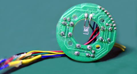
The SPI MP3 player circuit that I designed consists of an MCU and an audio IC. The MCU connects to the audio IC via SPI. It needs to stream MP3 data continuously for the audio IC to decode the data into audio signals. The mistake I made was placing an analog ground plane under the whole audio IC, and connecting the analog ground and the digital ground of the MCU between the two components.
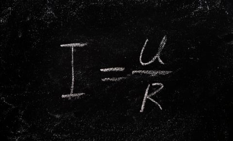
This caused the digital SPI signals to run closely, and in parallel, to part of the analog ground and caused the SPI MP3 player coupling to the audio channel to have interference. Now, we often treat signals and ground as two different entities in design. however, in basic physics, the pulses of zeros and ones are made up of a complete current loop. In this case, the return path for SPI MP3 player signals crossed the analog ground that was supposed to be free from digital noise.
How Shifting the Digital and Audio Ground Boundary Eliminate the Noise Interference
I didn’t take any chances on the second revision and went through the technical guide of the audio IC three times. Some ICs will have analog and digital ground coming out of the package. These terms are misleading, because they often refer to the inner workings of the chip, and should be tied together immediately on the outside of the package. The connection of these two grounds should then become the single point where the analog and digital grounds connect. Then the return current paths for the two planes will not cross each other and interfere with any signals. With the SPI signals having their return path clearly on the digital ground, I said a quick prayer and produced my second batch of revised MP3 players. Thankfully, there were no rude shocks in these new production units.
When you need to access an easy-to-use PCB layout tool that includes everything needed to build high-quality manufacturable MP3 player circuit boards, look no further than CircuitMaker. All CircuitMaker users also have access to a personal workspace on the Altium 365 platform. You can upload and store your design data in the cloud, and you can easily view your projects via your web browser in a secure platform.
Start using CircuitMaker today and stay tuned for the new CircuitMaker Pro from Altium.
Related Resources
Related Technical Documentation
Table of Contents
Multidisciplinary Product Creation
- Align data and context across every discipline
- Collaborate concurrently with no silos
- Make faster decisions with shared visibility
- Stay connected through real-time updates
Learn More
Thank you, you are now subscribed to updates.