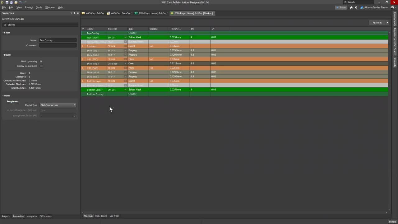

Mobile menu
  • Solutions
    • Octopart Discover Go beyond part search to discover viable solutions, evaluate tradeoffs, and make better decisions earlier
    • Altium Develop Design advanced PCBs in Altium Designer, working independently or connecting reviewers, sourcing data, and release coordination when needed
    • Altium Agile Teams Bring structure to multidisciplinary electronics development and collaboration without sacrificing speed
    • Altium Agile Enterprise Connect context from intent through release with an intelligent, governed, extensible platform
  • Resources & Support
    Free Altium 365 Tools
    • Gerber Compare
    • Online PCB Viewer
    Resources & Support
    • Learning Hub
    • Support Center
    • Documentation
    • Webinars
    Altium Community
    • Forum
    • Bug Crunch
    • Ideas
  • Education & Training
    • Student Lab Free access to professional PCB design software, training, and learning resources for students
    • Educator Center A comprehensive education platform providing curriculum, software, training, and classroom resources for educators
    • Altium Education Curriculum Free college- and university-level PCB design curriculum designed to prepare students for real-world engineering careers
    • Altium Professional Training Flexible on-demand and instructor-led training courses that help engineers build and advance their PCB design skills
  • Search Open
    Search Close
Sign In
Webinars

Main menu

  • Home
  • PCB Design
    • Collaboration
    • Component Creation
    • Data Management
    • Design Outputs
    • ECAD/MCAD
    • HDI Design
    • High Speed Design
    • Multi-Board
    • PCB Layout
    • PCB Routing
    • PCB Supply Chain
    • Power Integrity
    • RF Design
    • Rigid Flex
    • Schematic Capture
    • Signal Integrity
    • Simulation
  • Software
    • Discover
    • Develop
    • Agile Teams
    • Agile Enterprise
    • Altium 365
    • Altium Designer
  • Education
    • Programs
    • Altium Academy
    • Engineering News
    • Guide Books
    • Newsletters
    • Podcasts
    • Projects
    • Training Courses
    • Webinars
    • Whitepapers
Learning Hub Webinars From '0' to Gerber in 36.5 minutes

From '0' to Gerber in 36.5 minutes

See how easy it is to create a prototype from scratch, automatically generate manufacturing files and standardized documentation in only 36.5 minutes - and all of this by only using the tools included in the unified design environment of Altium Designer 20.

WE WILL SHOWCASE THE FOLLOWING:

  • Schematic entry and component selection
  • Generating a bill of material with current supplier information from the field
  • PCB-Design and board outline fitting in 3D
  • Generating manufacturing files and documentation

Discover how fast you can walk through a complete design cycle by using just one tool. All steps will be explained and showcased, right up to the generation of manufacturing and documentation files.

Gerber

Registration has recently closed. Check back soon for on-demand webinar.

Related Resources

From Complexity to Clarity: Smart Design Reviews for Agile Engineering Teams Smart Design Reviews speed up your design process
Multiple Dates and Times October 8, 2026 2:00 PM Register
01:00:30 Introducing the Requirements & Systems Portal Watch our webinar to learn about the application of the Altium 365 suite. Requirements & Systems Portal will help align engineering teams to get to market quicker Watch Video
00:33:28 Make Better Design Decisions with Signal and Power Integrity Insight See how Signal and Power Analysis within Altium Agile Teams helps engineering teams reduce late-stage surprises and improve design outcomes. Watch Video
Ciiva Search, Analysis And Management Ciiva Search, Analysis And Management

Ciiva Search, Analysis And Management

Watch Video
00:39:52 Sustainability & Energy Efficiency in Electronic Product Development Watch Video
00:44:59 Streamline your customer relation with Altium 365 Enterprise Join our webinar designed for engineers and users in EMS companies Watch Video
00:37:54 Safety & Reliability in Electronics Design – Strategies, Standards & Tools How can development teams and decision-makers effectively implement safety, security, and compliance without delaying innovation? Watch Video
00:41:02 Altium Customization with Scripting or Low-Code See how scripting, low-code, no-code, and API integrations can help you work more efficiently—without extra setup or complex systems. Watch Video
44:22 Digitally Connecting ECAD-MCAD Collaboration

Collaborative product development between the Electronic and Mechanical design domains brings unique challenges. Today, most companies are still using a file-based methodology (STEP, IDF, DXF, IDX) for creating and exchanging data between the two domains. This, for the most part, requires that the entire database is exchanged multiple times, resulting in README files, marked-up PDF’s and in-person meetings to review the updates and ensure they

Watch Video
00:32:02 ECAD Engineering Management Beyond Design Connecting Requirements, Development, and PLM in One Enterprise Workflow Watch Video

Related Technical Documentation

Altium 365 Platform Interface Altium 365 Platform Interface

Depending on your relationship with Altium, the services offered on the Altium Platform will be experienced from within Altium Designer and through the platform's browser-based interface. This page takes a look at the latter and provides an overview of what you'll see when you register an Altium Account and sign in to the Altium Platform Interface. For the latest information on the security,…

Read Documentation
New in Requirements Portal New in Requirements Portal

Requirements Portal is under continuous development. This page outlines new features and enhancements made to Requirements Portal in key updates. Update - 21 September 2026 This release includes bug fixes to enhance the overall functionality and user experience. Update - 3 September 2026 [collapse collapsed class="" title="Key Highlights" id="key_highlights_update_3_september_2026" data-inclusion…

Read Documentation
Understanding Harness Synchronization – Advanced Users Understanding Harness Synchronization – Advanced Users

How MCAD CoDesigner supports Harness Design MCAD CoDesigner’s Harness support integrates the ECAD and MCAD models of the harness. The goal is to allow the harness geometry to be designed in MCAD and then transferred back to ECAD, as the physical parameters (lengths) of the harness elements. The common (and essentially similar) element between the ECAD and MCAD environments is that the schematic…

Read Documentation
Synchronizing a Harness Design Project Synchronizing a Harness Design Project

Accessing the ECAD-MCAD Harness Synchronization Capabilities Note that not all features described on this page are available in all installations of Altium MCAD CoDesigner. Refer to the Feature Availability panel on the right for more information. Harness synchronization is currently available for PTC Creo (MCAD CoDesigner 3.5 and later) and SOLIDWORKS (MCAD CoDesigner 3.6 and later), support for…

Read Documentation
Preparing Siemens NX for CoDesign Preparing Siemens NX for CoDesign

Altium CoDesigner for Siemens® NX™ is only available for designers with an Altium Enterprise Solution. Altium CoDesigner for Siemens NX moved out of Beta in Altium CoDesigner 3.0. Altium CoDesigner is an interface for transferring printed circuit board designs between the ECAD and MCAD design domains. Once the CoDesigner add-in has been added to your MCAD software, CoDesigner can pass design…

Read Documentation
Preparing SOLIDWORKS for CoDesign Preparing SOLIDWORKS for CoDesign

Parent page: Installing & Configuring Altium CoDesigner Altium CoDesigner is an interface for transferring printed circuit board designs between the ECAD and MCAD design domains. Once the CoDesigner add-in has been added to your MCAD software, CoDesigner can pass design changes back and forth. Design changes are passed through an Altium Workspace, which acts as a bridge between the ECAD and MCAD…

Read Documentation
Preparing PTC Creo for CoDesign Preparing PTC Creo for CoDesign

Altium CoDesigner is an interface for transferring printed circuit board designs between the ECAD and MCAD design domains. Once the CoDesigner add-in has been added to your MCAD software, CoDesigner can pass design changes back and forth between your MCAD software and your Altium ECAD software. Design changes are passed through an Altium Workspace, which acts as a bridge between the ECAD and MCAD…

Read Documentation
Preparing Autodesk Inventor for CoDesign Preparing Autodesk Inventor for CoDesign

Altium CoDesigner is an interface for transferring printed circuit board designs between the ECAD and MCAD design domains. Once the CoDesigner add-in has been added to your MCAD software, CoDesigner can pass design changes back and forth. Design changes are passed through an Altium Workspace, which acts as a bridge between the ECAD and MCAD domains. ► Check the version compatibility between your…

Read Documentation
Preparing Autodesk Fusion for CoDesign Preparing Autodesk Fusion for CoDesign

Altium CoDesigner is an interface for transferring printed circuit board designs between the ECAD and MCAD design domains. Once the CoDesigner add-in has been added to your MCAD software, CoDesigner can pass design changes back and forth. Design changes are passed through an Altium Workspace, which acts as a bridge between the ECAD and MCAD domains. ► Check the version compatibility between your…

Read Documentation
New in CoDesigner New in CoDesigner

Altium's MCAD CoDesigner technology connects the mechanical and electrical design domains, allowing the mechanical and electronic engineers to pass the loaded PCB back and forth between the two domains. In your Altium design software, this is achieved through an extension that loads and extracts board and component data from the PCB editor, the MCAD CoDesigner extension. In the MCAD software the…

Read Documentation

From '0' to Gerber in 36.5 minutes

Created: July 20, 2020
At a Glance
See how easy it is to create prototypes from scratch and automatically generate manufacturing files and standardized documentation using Altium Designer.
Go Deeper with AI:
ChatGPT Perplexity Claude Gemini Grok
6 videos
  • Hosted by Danny Goddard - Field Application Engineer
    01:31:52 • Dec 29, 2020
    Hosted by Danny Goddard - Field Application Engineer
    01:31:52 • Dec 29, 2020

    See how easy it is to create prototypes from scratch and automatically generate manufacturing files and standardized documentation in 36.5 minutes using Altium Designer.
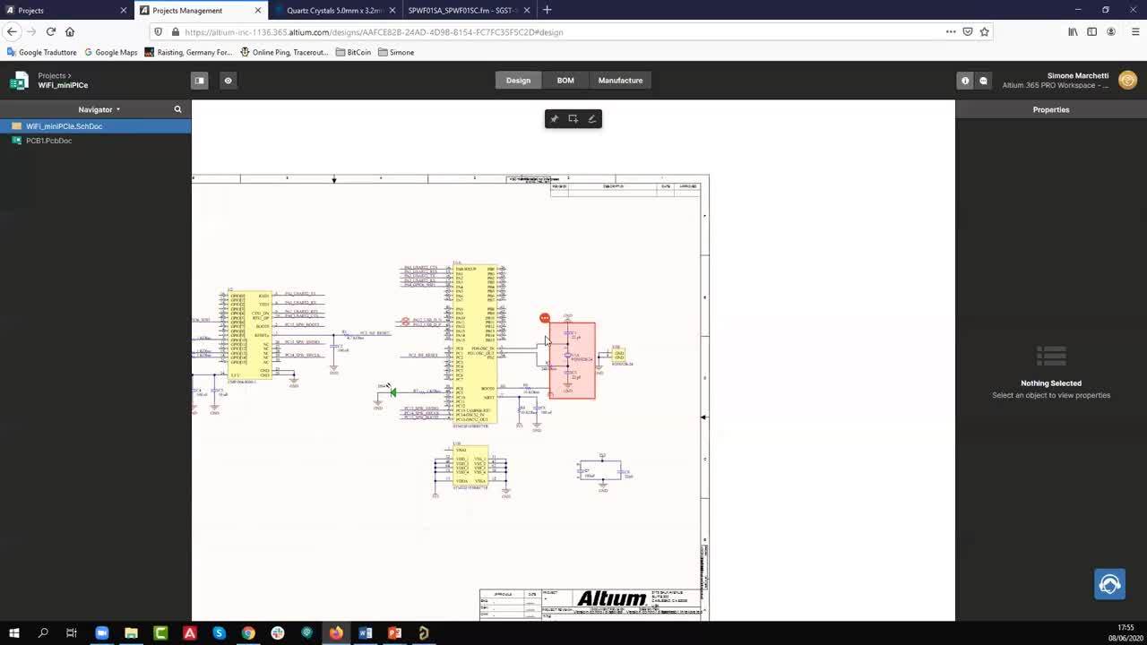
  • Presentato da Simone Marchetti - Field Application Engineer
    00:53:16 • Dec 30, 2020
    Presentato da Simone Marchetti - Field Application Engineer
    00:53:16 • Dec 30, 2020

    Scoprite com'è facile creare prototipi da zero e generare automaticamente file di produzione e documentazione standardizzata con Altium Designer.
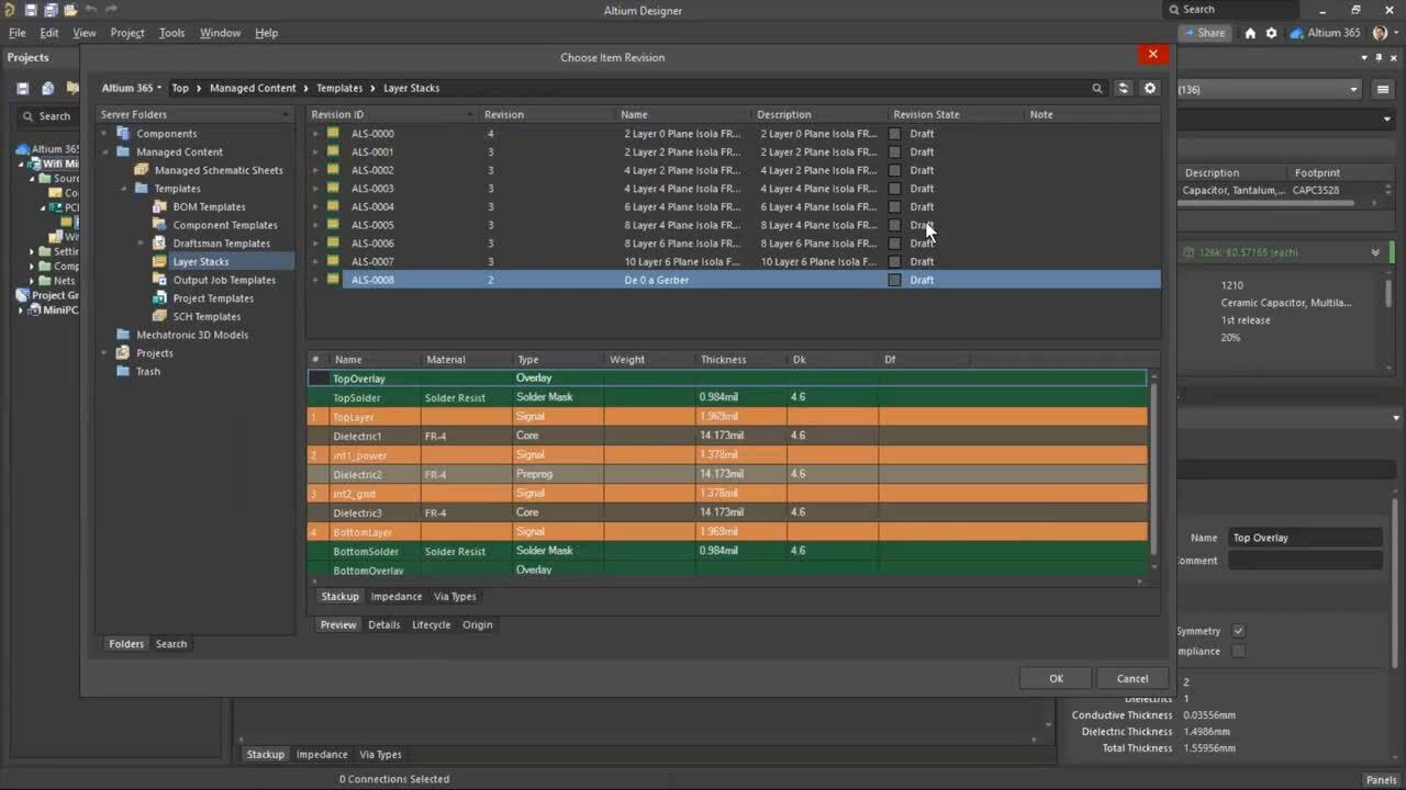
  • Presentado por Antonio Becerra Esteban - Field Application Engineer
    00:52:57 • Dec 30, 2020
    Presentado por Antonio Becerra Esteban - Field Application Engineer
    00:52:57 • Dec 30, 2020

    Vea lo fácil que es crear prototipos desde cero y generar automáticamente archivos de fabricación y documentación estandarizada utilizando Altium Designer.
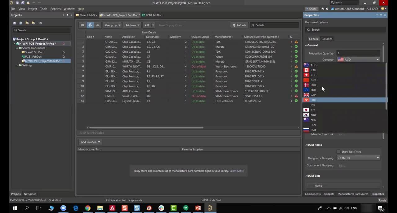
  • Présenté par Nourhene Kerkeni - Field Application Engineer
    01:15:42 • Dec 30, 2020
    Présenté par Nourhene Kerkeni - Field Application Engineer
    01:15:42 • Dec 30, 2020

    Voyez comme il est facile de créer des prototypes à partir de zéro et de générer automatiquement des fichiers de fabrication et une documentation standardisée à l'aide d'Altium Designer.
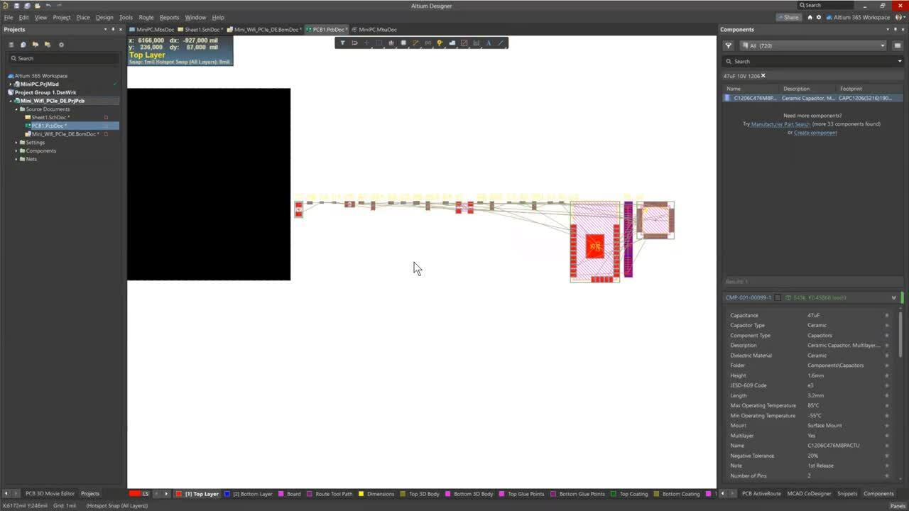
  • Präsentiert von Antonio Becerra Esteban - Field Application Engineer
    00:48:57 • Dec 29, 2020
    Präsentiert von Antonio Becerra Esteban - Field Application Engineer
    00:48:57 • Dec 29, 2020

    Sehen Sie, wie einfach es ist, mit Altium Designer Prototypen von Grund auf zu erstellen und automatisch Fertigungsdateien und standardisierte Dokumentation zu generieren.
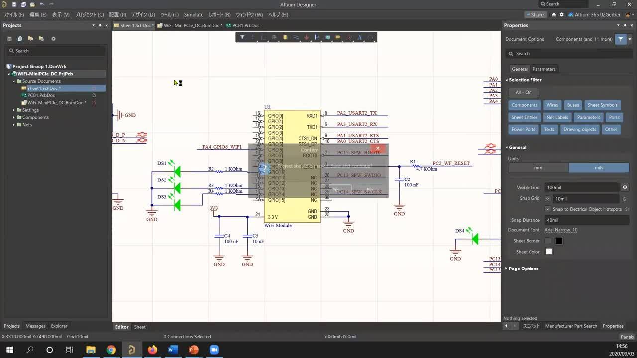
  • プレゼンター:ダニエル チョウ
    01:03:25 • Dec 29, 2020
    プレゼンター:ダニエル チョウ
    01:03:25 • Dec 29, 2020

    このオンデマンドWebセミナーでは、Altium Designer 20 を使用して、プロトタイプをゼロから作成し、製造ファイルや標準化されたドキュメントを 36.5分で自動的に生成することがいかに簡単かつ迅速にできるかを紹介します。

Product: Altium Designer Webinars Electrical Engineers Gerber Manufacturing Outputs and Compliance
Other Recordings
Clear ×
Region
Language

See how easy it is to create a prototype from scratch, automatically generate manufacturing files and standardized documentation in only 36.5 minutes - and all of this by only using the tools included in the unified design environment of Altium Designer 20.

WE WILL SHOWCASE THE FOLLOWING:

  • Schematic entry and component selection
  • Generating a bill of material with current supplier information from the field
  • PCB-Design and board outline fitting in 3D
  • Generating manufacturing files and documentation

Discover how fast you can walk through a complete design cycle by using just one tool. All steps will be explained and showcased, right up to the generation of manufacturing and documentation files.

Author

Author

Nourhene is an Electronic Engineer specializing in PCB Design and FPGA Programming, holding a Master’s degree in RFID technologies. Since joining Altium in 2019, she has partnered closely with the sales team to support both prospects and existing customers through technical sales and marketing initiatives across Altium’s portfolio.

Before Altium, Nourhene designed complex PCBs for Automotive and Aerospace applications at large international companies, where she also managed comprehensive testing processes. She has extensive experience collaborating with PCB manufacturers across Europe and Asia. Nourhene holds CID certification and is a certified Altium Designer Trainer.

More content by Nourhene Kerkeni

Author

Author

Daniel joined Altium in 2019 as an Application engineer and moved into the Technical Sales role in the same year. Daniel provides technical assistance for sales, third party distributors, and customers in the Asia Pacific region (APAC) and is based in the Altium Tokyo, Japan office. Daniel has experience with PCB,  FPGA, and ASIC design in telecommunication and Information industries. 
 

More content by Daniel Cho

Related Resources

From Complexity to Clarity: Smart Design Reviews for Agile Engineering Teams Smart Design Reviews speed up your design process
Multiple Dates and Times October 8, 2026 2:00 PM Register
01:00:30 Introducing the Requirements & Systems Portal Watch our webinar to learn about the application of the Altium 365 suite. Requirements & Systems Portal will help align engineering teams to get to market quicker Watch Video
00:33:28 Make Better Design Decisions with Signal and Power Integrity Insight See how Signal and Power Analysis within Altium Agile Teams helps engineering teams reduce late-stage surprises and improve design outcomes. Watch Video
Ciiva Search, Analysis And Management Ciiva Search, Analysis And Management

Ciiva Search, Analysis And Management

Watch Video
00:39:52 Sustainability & Energy Efficiency in Electronic Product Development Watch Video
00:44:59 Streamline your customer relation with Altium 365 Enterprise Join our webinar designed for engineers and users in EMS companies Watch Video
00:37:54 Safety & Reliability in Electronics Design – Strategies, Standards & Tools How can development teams and decision-makers effectively implement safety, security, and compliance without delaying innovation? Watch Video
00:41:02 Altium Customization with Scripting or Low-Code See how scripting, low-code, no-code, and API integrations can help you work more efficiently—without extra setup or complex systems. Watch Video
44:22 Digitally Connecting ECAD-MCAD Collaboration

Collaborative product development between the Electronic and Mechanical design domains brings unique challenges. Today, most companies are still using a file-based methodology (STEP, IDF, DXF, IDX) for creating and exchanging data between the two domains. This, for the most part, requires that the entire database is exchanged multiple times, resulting in README files, marked-up PDF’s and in-person meetings to review the updates and ensure they

Watch Video
00:32:02 ECAD Engineering Management Beyond Design Connecting Requirements, Development, and PLM in One Enterprise Workflow Watch Video

Related Technical Documentation

Altium 365 Platform Interface Altium 365 Platform Interface

Depending on your relationship with Altium, the services offered on the Altium Platform will be experienced from within Altium Designer and through the platform's browser-based interface. This page takes a look at the latter and provides an overview of what you'll see when you register an Altium Account and sign in to the Altium Platform Interface. For the latest information on the security,…

Read Documentation
New in Requirements Portal New in Requirements Portal

Requirements Portal is under continuous development. This page outlines new features and enhancements made to Requirements Portal in key updates. Update - 21 September 2026 This release includes bug fixes to enhance the overall functionality and user experience. Update - 3 September 2026 [collapse collapsed class="" title="Key Highlights" id="key_highlights_update_3_september_2026" data-inclusion…

Read Documentation
Understanding Harness Synchronization – Advanced Users Understanding Harness Synchronization – Advanced Users

How MCAD CoDesigner supports Harness Design MCAD CoDesigner’s Harness support integrates the ECAD and MCAD models of the harness. The goal is to allow the harness geometry to be designed in MCAD and then transferred back to ECAD, as the physical parameters (lengths) of the harness elements. The common (and essentially similar) element between the ECAD and MCAD environments is that the schematic…

Read Documentation
Synchronizing a Harness Design Project Synchronizing a Harness Design Project

Accessing the ECAD-MCAD Harness Synchronization Capabilities Note that not all features described on this page are available in all installations of Altium MCAD CoDesigner. Refer to the Feature Availability panel on the right for more information. Harness synchronization is currently available for PTC Creo (MCAD CoDesigner 3.5 and later) and SOLIDWORKS (MCAD CoDesigner 3.6 and later), support for…

Read Documentation
Preparing Siemens NX for CoDesign Preparing Siemens NX for CoDesign

Altium CoDesigner for Siemens® NX™ is only available for designers with an Altium Enterprise Solution. Altium CoDesigner for Siemens NX moved out of Beta in Altium CoDesigner 3.0. Altium CoDesigner is an interface for transferring printed circuit board designs between the ECAD and MCAD design domains. Once the CoDesigner add-in has been added to your MCAD software, CoDesigner can pass design…

Read Documentation
Preparing SOLIDWORKS for CoDesign Preparing SOLIDWORKS for CoDesign

Parent page: Installing & Configuring Altium CoDesigner Altium CoDesigner is an interface for transferring printed circuit board designs between the ECAD and MCAD design domains. Once the CoDesigner add-in has been added to your MCAD software, CoDesigner can pass design changes back and forth. Design changes are passed through an Altium Workspace, which acts as a bridge between the ECAD and MCAD…

Read Documentation
Preparing PTC Creo for CoDesign Preparing PTC Creo for CoDesign

Altium CoDesigner is an interface for transferring printed circuit board designs between the ECAD and MCAD design domains. Once the CoDesigner add-in has been added to your MCAD software, CoDesigner can pass design changes back and forth between your MCAD software and your Altium ECAD software. Design changes are passed through an Altium Workspace, which acts as a bridge between the ECAD and MCAD…

Read Documentation
Preparing Autodesk Inventor for CoDesign Preparing Autodesk Inventor for CoDesign

Altium CoDesigner is an interface for transferring printed circuit board designs between the ECAD and MCAD design domains. Once the CoDesigner add-in has been added to your MCAD software, CoDesigner can pass design changes back and forth. Design changes are passed through an Altium Workspace, which acts as a bridge between the ECAD and MCAD domains. ► Check the version compatibility between your…

Read Documentation
Preparing Autodesk Fusion for CoDesign Preparing Autodesk Fusion for CoDesign

Altium CoDesigner is an interface for transferring printed circuit board designs between the ECAD and MCAD design domains. Once the CoDesigner add-in has been added to your MCAD software, CoDesigner can pass design changes back and forth. Design changes are passed through an Altium Workspace, which acts as a bridge between the ECAD and MCAD domains. ► Check the version compatibility between your…

Read Documentation
New in CoDesigner New in CoDesigner

Altium's MCAD CoDesigner technology connects the mechanical and electrical design domains, allowing the mechanical and electronic engineers to pass the loaded PCB back and forth between the two domains. In your Altium design software, this is achieved through an extension that loads and extracts board and component data from the PCB editor, the MCAD CoDesigner extension. In the MCAD software the…

Read Documentation
Back to Home
Altium logo

Solutions for Every Role and Team

  • Discover and evaluate design options earlier

  • Develop in one shared workspace

  • Scale with control and compliance

  • Connect every stage of hardware development

Learn More

Platform-based Solutions
  • Octopart Discover
  • Altium Develop
  • Altium Agile Teams
  • Altium Agile Enterprise
Tools
  • Altium Designer
  • Octopart
Platform
  • Altium 365
Company
  • Our Customers
  • Trust Center
  • Newsroom
Software Capabilities
  • PCB Layout and Design
  • Requirements Management
  • Electronics Data Management
  • IT Security
  • Electronics Manufacturing
  • Electronics Supply Chain
  • Engineering Management
Resources & Support
  • Status
  • Downloads
  • Learning Hub
  • Support Center
  • Bug Crunch
  • Forum
  • Documentation
  • Ideas
  • Education
  • Professional Training / Certification
  • Webinars
  • Beta Program
Education
  • Student Lab
  • Educator Center
  • Altium Education Curriculum
Careers
  • Career at Altium
  • Copyrights & Trademark
  • Privacy policy
  • Cookie policy
  • Terms of Service
  • Legal
© 2026 Altium LLC.