Bridging Mechanical and Electrical Teams for Smarter Automotive Design

At a Glance
Unify ECAD and MCAD teams for smarter automotive design. Learn how real-time collaboration reduces rework and drives innovation in vehicle electronics.


Modern automobiles are essentially sophisticated electronic systems on wheels. A luxury car today can host over a hundred electronic control units (ECUs) networked throughout the vehicle, and the wiring harnesses connecting them often stretch for several kilometers in total length. All these electronics must seamlessly integrate with the vehicle’s mechanical structure and constraints.
However, design teams responsible for the electronics (ECAD) and those handling mechanical design (MCAD) have traditionally worked in silos. The disconnect is increasingly untenable as smarter automotive design demands tight coordination between electrical and mechanical domains. Bridging these teams is now a necessity to deliver complex automotive projects on time and error-free.
Key Takeaways
- Automotive electronics complexity demands tighter ECAD–MCAD integration. Modern vehicles rely on hundreds of ECUs and kilometers of wiring, making close coordination between electrical and mechanical teams essential to avoid errors and delays.
- Siloed, file-based workflows drive rework and schedule risk. Manual handoffs, disconnected tools, and format conversions lead to data loss, late-stage fit issues, and repeated design iterations.
- Wire harness design is inherently cross-domain. Accurate harness routing, connector placement, and wire length estimation require synchronized electrical connectivity and 3D mechanical context to prevent costly mistakes.
- Real-time ECAD–MCAD co-design improves first-pass success: Bidirectional synchronization of PCBs and harnesses enables accurate 3D routing, eliminates manual length estimation, reduces rework, and accelerates automotive design cycles.
Roadblocks in Automotive Design: Siloed Workflows
When ECAD and MCAD teams operate on separate tracks, miscommunication and misalignment inevitably creep in. In a conventional workflow, a PCB designer might send board outlines or connector placements to a mechanical engineer via exported files, and the mechanical team might return enclosure models or mounting requirements the same way. These hand-offs are labor-intensive and prone to error. Some common challenges that arise from such siloed workflows include:
- Data Transfer Errors: Disparate file formats and manual import/export steps often lead to lost or misinterpreted data. Relying on emails and file conversions for design updates increases the risk of inconsistencies between the electrical and mechanical models.
- Design Rework: Lack of synchronization means issues are caught late. It’s not uncommon to discover that a PCB doesn’t fit the housing or that a connector is misaligned, forcing engineers to redo work. The back-and-forth of continually importing and converting files adds hours of manual labor and often results in repetitive rework.
- Project Delays: Inefficient ECAD-MCAD interaction can slow the entire design cycle. Teams often wait for updated files or spend time fixing translation problems, which in turn delays prototyping and product release. Fragmented workflows ultimately hinder time-to-market.
In automotive harness design, whether for specialized installations like police vehicle retrofits or for OEM programs such as EV platforms, these inefficiencies are especially visible.
Many engineers still rely on Microsoft Visio for harness drawings and Excel spreadsheets for connectivity data. Because these tools don’t communicate, migrating information between them is entirely manual and highly error-prone. It’s all too easy for an engineering decision to get lost when updates aren’t consistently reflected in both documents. While this process might suffice for a simple, low-volume build, it quickly breaks down as vehicles grow more complex and the number of connections multiplies.
This challenge isn’t hypothetical. There are entire tutorials on using Visio for wiring harnesses like this example, and Microsoft even provides documented workflows for creating electrical diagrams in Visio on their support site. While these methods can be useful for illustration, they aren’t scalable for modern automotive harness design. The lack of integration means designs are error-prone, disconnected from the mechanical reality of the vehicle, and lack a single source of truth.
Separated design domains thus create inefficiencies and errors that impact product quality and schedules.
ECAD-MCAD Collaboration in Wire Harness Design
Wire harnesses are the central nervous system of a vehicle, linking electronic devices across the car. Designing these harnesses is an inherently cross-domain task. Electrical engineers define the connectivity (which components need to be linked, and how), while mechanical engineers must ensure the physical routing of cables through the vehicle is feasible and safe.
In modern cars with high wiring density, a single harness can contain thousands of wires and dozens of connectors. An average mid-size car’s harness easily exceeds a thousand wires and 45 kg in weight. In high-end and electric vehicles, the total wire length can reach multiple kilometers, with EVs requiring roughly 50%-60% more wiring than traditional ICE vehicles. All of this wiring must be packaged into tight spaces: snaking through crammed engine compartments, dashboards, pillars, and underbody channels.
Tight packaging constraints pose huge challenges. Every bend, bracket, and grommet in the car’s mechanical design affects how the harness needs to be laid out. If the ECAD and MCAD teams work in isolation, errors are almost guaranteed.
For example, an electrical engineer might specify a cable length based on 2D schematics, only to have the mechanical team later discover the cable is too short to route along the complex 3D path in the chassis. Or a connector’s position on a PCB might make sense on the electrical drawing, but it could collide with a structural member in the physical vehicle. These disconnects lead to late-stage design changes, costly design rework, or even wiring issues that aren’t caught until prototyping - a nightmare scenario in the automotive industry.
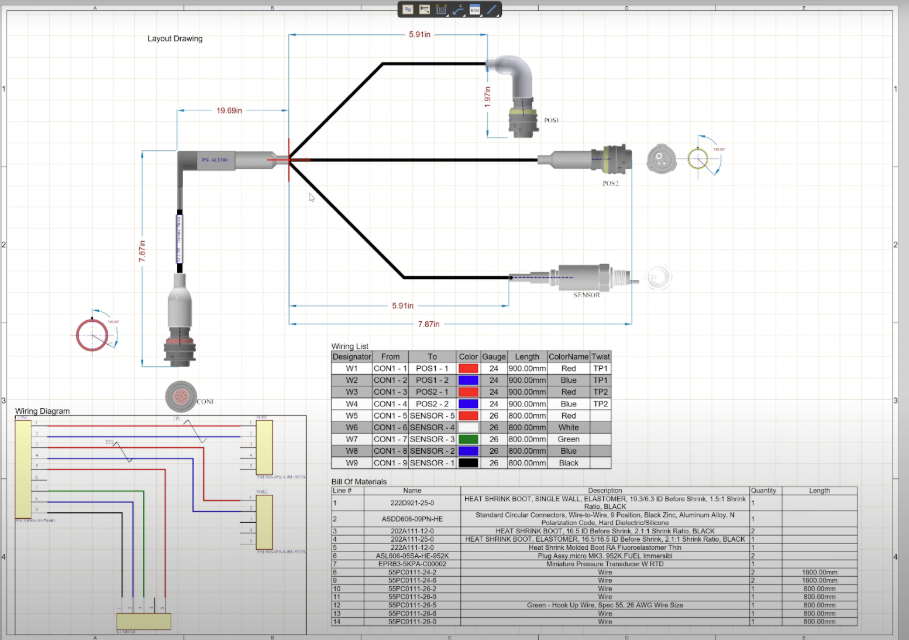
Another common issue arises around connector pinouts. Mechanical engineers are often left manually cross-referencing PDFs and schematics to figure out how an I/O board connects to a harness. This is slow, error-prone work, and it’s easy to misinterpret which pin carries which signal when information is scattered across tools. With synchronized harness and multi-board schematics in Altium Agile Teams, the pin mapping is crystal clear. Engineers see exactly how an I/O board interfaces with its connector, without guesswork. The data continues to propagate across ECAD and MCAD, preserving a single source of truth for both domains.
The solution is clear: real-time collaboration and synchronization between ECAD and MCAD for harness design. When both teams share a common design vision and data, the electrical team can design knowing the mechanical constraints, and vice versa. This is exactly where Altium’s ECAD-MCAD integration capabilities come into play, enabling cohesive wire harness design workflows that span both domains.
Bridging the Gap with MCAD Co-Design
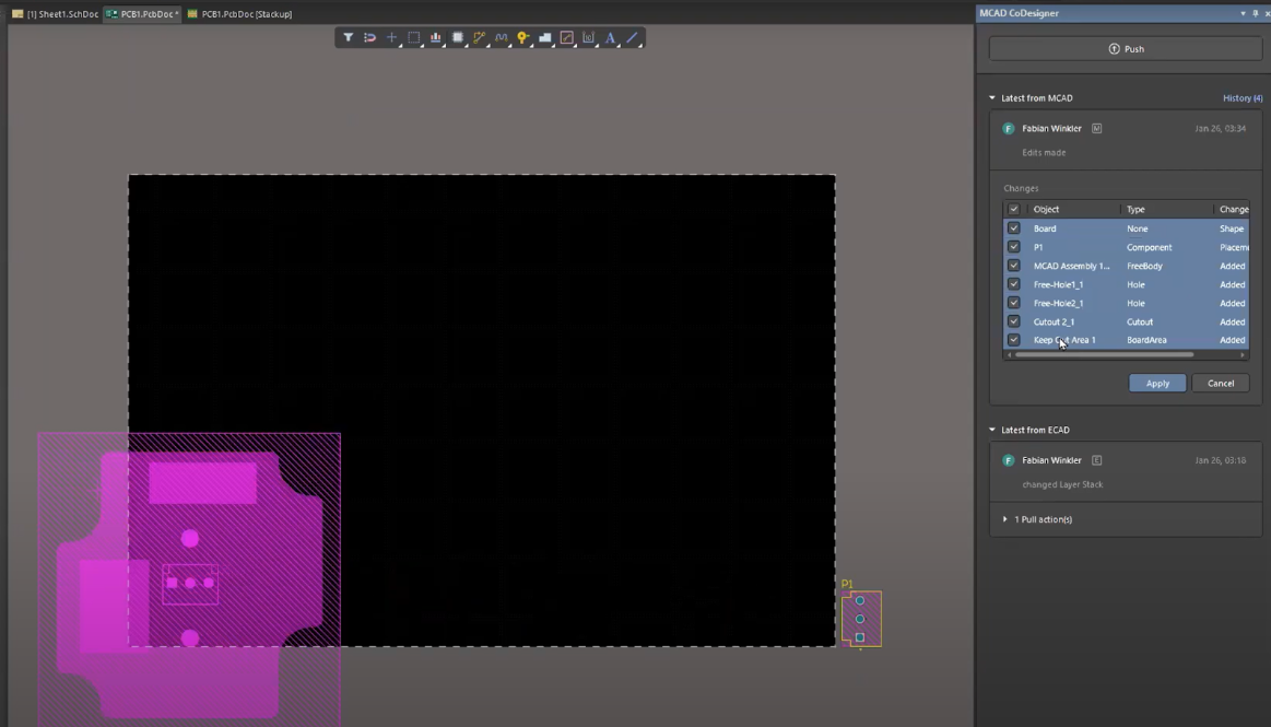
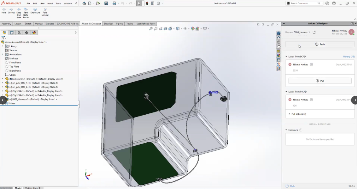
Altium’s MCAD co-design enables a seamless push-pull workflow between electrical and mechanical design environments. In the example below, a PCB assembly in SOLIDWORKS is synchronized with its enclosure in Altium Designer via the co-designer panel (shown in the MCAD interface on the right). Design changes (like board shape, component placement, or mounting holes) can be pushed from MCAD to ECAD and pulled in the other direction, ensuring both teams are always working with the latest 3D-accurate design.
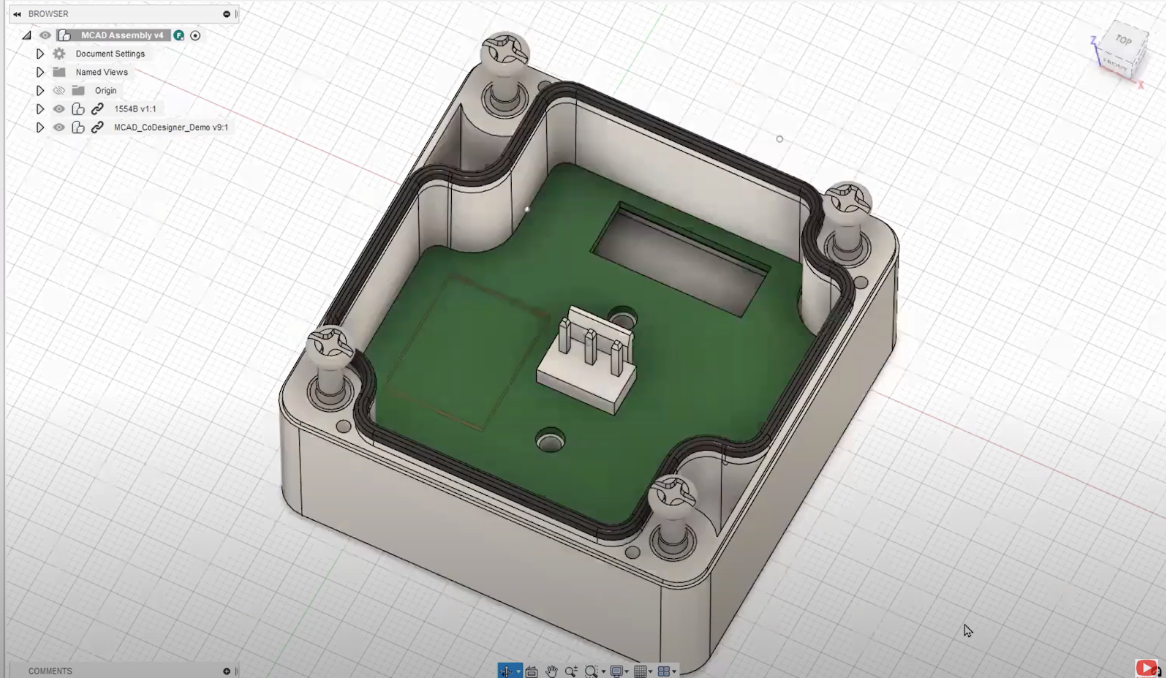
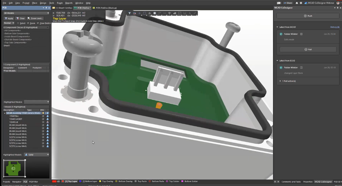
Altium's MCAD co-design bridges the ECAD-MCAD gap, linking Altium Designer (for PCB and harness) with popular mechanical CAD tools like SOLIDWORKS or PTC Creo. This allows electrical and mechanical engineers to work in their preferred environments, with real-time, bi-directional data exchange, eliminating manual file exports. Continuous synchronization ensures consistency of board shapes, component placements, hole locations, and multi-board assemblies between ECAD and MCAD.
MCAD co-design transmits precise design updates, using 3D models (Parasolid format) for PCB components and board geometries. A board designer can adjust the PCB outline or reposition connectors, while a mechanical engineer can tweak board location or add keep-out zones. Both sides remain in sync via a shared workspace, eliminating file versioning issues.
Harness Design Synchronization in Action
Altium’s MCAD co-design doesn’t stop at PCB board shape and component sync. It extends into the realm of cable harness design, which is a game-changer for automotive engineers. MCAD co-design now supports full wire harness project synchronization between Altium Designer and MCAD tools.
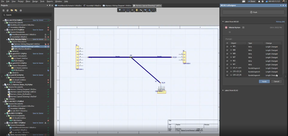
In practice, this means the electrical engineer can define the logical harness in Altium (wires, connectors, splices, “from-to” connectivity data, etc.), and seamlessly pass that data to the mechanical team for 3D routing. MCAD co-design will send all the necessary harness details from ECAD to MCAD, including the list of connectors, splice locations, and connectivity information. The mechanical engineer then routes the wires in the 3D CAD assembly, positioning wires along the vehicle frame, applying clips or grommets, and respecting bend radius and space constraints. Once the routing is done, the results are pushed back to ECAD. MCAD co-design transmits the physical attributes, like the exact wire lengths for each connection, and even the 3D harness model itself, back into Altium’s harness project. The electrical designer can pull these updates and have the true lengths and route geometry reflected in their harness documentation.
Traditionally, wire length estimation was a manual task. Mechanical engineers would route cables in CAD, then copy those lengths into a spreadsheet for the harness team. Manual wire length estimation led to errors and significant material waste in harness manufacturing due to miscalculations and copy-paste mistakes. Harness synchronization automates 3D routing to accurately calculate and back-annotate wire lengths, eliminating these issues.
Driving Smarter Automotive Design Through ECAD-MCAD Collaboration
As automotive systems grow more complex, separated electrical and mechanical design becomes obsolete. Integrated ECAD-MCAD workflows enable real-time synchronization between PCB designers and mechanical engineers, avoiding data errors, rework loops, and schedule slips. Tools like Altium's MCAD co-design let teams focus on innovation, confident that boards, wires, and mechanical parts will fit together exactly as intended.
Tighter ECAD-MCAD collaboration delivers competitive advantage through faster design cycles and higher first-pass success rates. When teams share live design data and iterate in unison, the result is a smarter design process that keeps pace with modern automotive demands. The right collaboration platform is key to driving the next generation of automotive electronics forward.
See what speed with structure looks like in practice. Start a free trial of Altium Agile Teams and explore how connected workflows, governed collaboration, and real-time visibility can transform the way your hardware team designs and delivers products.
Frequently Asked Questions
Why is ECAD–MCAD collaboration especially critical in automotive design?
Modern vehicles contain hundreds of ECUs and kilometers of wiring that must fit precisely within tight mechanical constraints. Without close ECAD–MCAD coordination, issues like connector collisions, incorrect cable lengths, or routing conflicts are often discovered late, leading to costly rework and delays.
What problems do siloed ECAD and MCAD workflows cause in wire harness design?
Siloed workflows rely on manual file exchanges, spreadsheets, and disconnected diagrams, which leads to data loss, version mismatches, and misinterpretation of connectivity or geometry. In harness design, this often results in incorrect wire lengths, misaligned connectors, and errors that surface during prototyping or manufacturing.
How does MCAD co-design improve wire harness accuracy?
MCAD co-design synchronizes logical harness data from ECAD (connectivity, pinouts, splices) with physical 3D routing in MCAD. Mechanical routing results, such as exact wire lengths and paths, are pushed back into ECAD automatically, eliminating manual calculations and reducing material waste and errors.
What are the tangible benefits of integrated ECAD–MCAD workflows for automotive teams?
Teams see fewer design iterations, reduced rework, faster prototyping, and higher first-pass success rates. Real-time synchronization ensures boards, connectors, and harnesses fit correctly within the vehicle, helping automotive projects stay on schedule while meeting increasing complexity and quality demands.

About Author
Related Resources


Related Technical Documentation


Table of Contents
- Key Takeaways
- Roadblocks in Automotive Design: Siloed Workflows
- ECAD-MCAD Collaboration in Wire Harness Design
- Bridging the Gap with MCAD Co-Design
- Harness Design Synchronization in Action
- Driving Smarter Automotive Design Through ECAD-MCAD Collaboration
- Frequently Asked Questions
- Why is ECAD–MCAD collaboration especially critical in automotive design?
- What problems do siloed ECAD and MCAD workflows cause in wire harness design?
- How does MCAD co-design improve wire harness accuracy?
- What are the tangible benefits of integrated ECAD–MCAD workflows for automotive teams?
Speed at Scale. Structured Repeatability. Secure Flexibility.
- Start up fast with out‑of‑the‑box workflows
- Collaborate using ECAD‑MCAD codesign tools
- Manage BOMs with live supply chain part data
- Manage access and security as teams scale
Contact Us
Thank you, you are now subscribed to updates.