


Types of Wiring Harnesses for Electronics


Many multi-board PCBs will not use board-to-board connectors or simple wired cables to make connections between PCBs. With just a pair of PCBs that need to connect to each other, a single cable or board-to-board connector will be enough. However, many products will use multiple PCBs that all connect with each other, and the number of cables involved can quickly become unmanageable inside an enclosure. The solution to keep all those wires and cables organized can be very simple: build a wiring harness.
Wiring harnesses come in all shapes and sizes, and they can become quite complex both mechanically and electrically. While there is a bit of design and assembly effort to create a wire harness that will work in an enclosure, wiring harnesses are worth the effort. This is especially true when a product goes into assembly, and you need to idiot-proof your cabling. So, if you're wondering what kind of wiring harness you might use in your product, take a look at these options.
Point-to-Point Cable Bundles
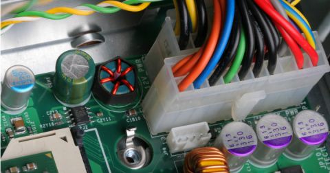
The simplest type of wiring harness uses point-to-point cable bundles and packages them together into a single harness assembly. Cable bundles can be packed together using adhesives, tapes, sheathing, or mesh jackets. The cables used in these bundles could be off-the-shelf cables, custom cables, or a combination of these. Interconnect topology that usually arises from this is point-to-point because of the direct connections via these cables.

Bifurcated Cables
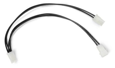
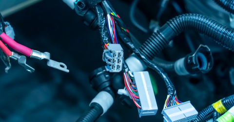
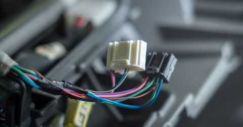
Cabling coming off of a connector can be bifurcated, where a single connector has wiring splitting off to two different destinations. This would be used to have a single receptacle on one PCB connecting to at least two other PCBs. This is a more sophisticated type of wiring harness that involves mixing and matching connectors and receptacles across different boards.
Simple bifurcated cable
Flex Printed Circuit (FPC) Cable
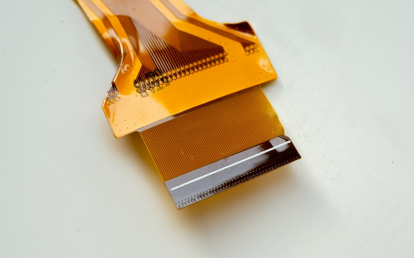
Flex ribbons can also be used as wiring harnesses, which would allow a mix of edge connectors, surface mount connectors, and even through-hole connectors to interface with a group of PCBs. Flex connectors have an advantage and that they are very flat and so they may be useful in very low profile products. In some products, a wire bundle in a standard wiring harness simply won't fit in the design, so a flex cable becomes a very attractive option.
Custom flex cables used as harnesses can have multiple branches going to receptacles on different PCBs.
When used as a wiring harness, the flex cable follows the same design rules as a flex PCB. The main difference here is the selection of connectors on the flex cable. Connectors on flex cables that plug into PCB receptacles should generally not be surface mounted if the flex ribbon will plug and unplug repeatedly. The reason is that the flexible polyamide could easily separate from the SMD pads. Instead, opt for SMD connectors that have a through-hole mounting assist or a through-hole welding tab, as this will prevent solder fracture near the connector plug and it will allow the cable to be connected and disconnected repeatedly.
Parts for Wiring Harnesses: Connectors and Crimps
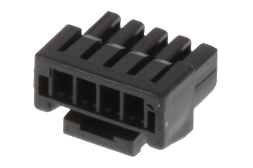
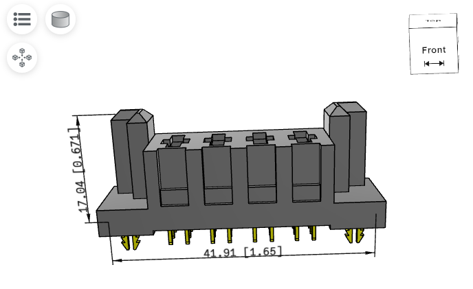
If you want to build a wiring harness, such as using bifurcated cables, you will need to select receptacles and mating connectors in order to make the required connections. Connector vendors do not normally specify their plug connectors as being used for wiring harnesses. Typically, these are crimp connectors that allow an assembler to attach a wire and then build out a cable assembly or wiring harness. For example, take a look at the Molex connector below.
This connector (Molex part number 5055651401) uses crimps for wire attachment, which could be integrated into a custom wiring harness.
A wiring harness can be easily built from this connector by using crimp contacts, which slide into the connector. The crimp contact will crimp onto a wire, and this allows the wire to slide in and secure itself inside the connector body. Once the connector is mated to its receptacle on a PCB, the required electrical connection is completed.
For a wiring harness assembler, the PCB and product documentation will need to include these parts for the wiring and harness components in the BOM. You will need to include:
- The part number for the mating connector in the wiring harness
- A part number for the required crimp contacts
- A part number for the wiring, including wire gauge
This can be included in the product's full BOM. I also like to include this information directly in the schematic for the connecting PCB so that there is no question as to what is the mating connector, crimp, or wiring. Some crimps require special crimp tools with their own part number, and these part numbers should also be included in the documentation.
These materials will need to be supplied to a wiring harness assembler so that a full wiring harness can be procured. The wiring harness should probably also have its own bill of materials, and it will need a detailed drawing showing pin connections on each connector plug, as well as part numbers for compatible crimps. Documentation of wiring harnesses can be difficult and may require some manual drawing due to the lack of standardization. Contact your cable assembly or wiring harness manufacturer to make sure you provide them with the documentation they need to correctly assemble your wiring harness.
Leverage MCAD collaboration for Sizing Cabling
When building a custom wiring harness or cable assembly, designers historically resorted to running cabling through a prototype enclosure using spooled wire or even string. A harness would then have to be hand-assembled in order to check to see that it would fit in the enclosure. If a flex cable was being used as a harness, then a flex prototype would need to be built, something which can be quite expensive with thin polyimide flex ribbons.
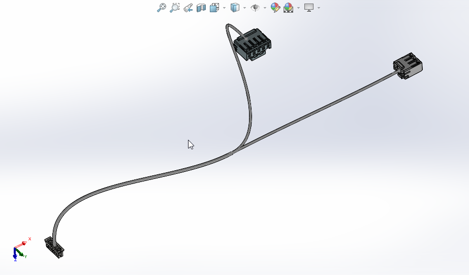
Obviously, this is expensive and time-consuming, especially when you are simply trying to estimate the wiring length inside the enclosure. Today's design teams should instead leverage MCAD applications and 3D models of the enclosure in order to estimate and size cabling. These tools can easily draw in the cabling of various shapes and sizes, as well as insert bends to visualize cable paths within a wiring harness.
Wiring harness designed in SolidWorks
The side benefit of this is it also allows experimentation with connector placement in a 3D mechanical model of the PCB within the enclosure. 3D models of connectors, such as STEP models, are widely available from most connector manufacturers and can be quickly used in ECAD and MCAD applications.
The weld tabs on this locking clip connector (Samtec part number PES-04-01-S-VT-LC) provide extra reinforcement for any flex cable-mounted interface connectors.
Whether you're building power electronics or advanced digital systems for commercial applications, Altium provides a comprehensive suite of PCB design features and world-class CAD tools. To enable effective collaboration in today’s cross-disciplinary environment, innovative companies rely on Altium to seamlessly share design data and accelerate the transition from design to manufacturing.
Want to seamlessly design wiring for your harness? Experience the power of wire harness design in Altium Develop.
About Author
Related Resources
Related Technical Documentation
Table of Contents
Design to Release, Without the Friction
- Keep reviews tied to the right version
- Reduce handoff confusion and rework
- Spot sourcing and release risk earlier
- Work solo, share when needed
Get Started
Thank you, you are now subscribed to updates.


