


Centralized Component Libraries – Best Practices for Hardware Teams

At a Glance
Standardize parts with centralized component libraries that unify symbols, footprints, lifecycles, alternates. Cut errors, quote delays, and redesign risk.


Here is something nobody told me until I was four years into my freelance career as a hardware engineer: the parts library and managing it well are the real bottleneck in PCB design.
It’s not so much the circuit design or even the PCB layout. It’s the parts, their availability, and their suitability.
I, along with other engineers, have spent hours or days looking for the right connectors and headers in a library because we didn’t know which version was correct.
I’ve had boards held up for weeks because resistors, capacitors, and other passives had the wrong manufacturer part number, no stock, or were EOL. I’ve also seen mid-quote situations where a chip came through as NRND or EOL in a BOM management tool.
These problems take a huge chunk of time even after the PCB layout is done. Unfortunately, given the number of parts in any BOM, these situations occur with high probability; they are not rare exceptions.
In this article, we’ll explore best practices for building and maintaining centralized component libraries so your hardware team can move faster and avoid production surprises.
Key Takeaways
- Poorly managed or decentralized component libraries are a major bottleneck in PCB design, often causing more delays than schematic or layout work.
- When every engineer manages parts differently, you get duplicate parts, inconsistent footprints, and missing 3D models, which leads to errors and wasted time during quoting and production.
- A powerful centralized system needs a clear part-creation workflow, standardized symbols and footprints, strict version control, and defined review/approval roles.
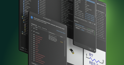
- Effective centralized libraries include capabilities like part previews, usage tracking across designs, lifecycle/status visibility, ecosystem-wide updates, comments, and the latest stock and availability checks.
- Ongoing maintenance plus clear access and permissions ensures the library stays accurate, supports alternates, and keeps hardware projects moving without last-minute supply chain surprises.
What Happens When Everyone Does Their Own Thing
Say you have five engineers. Each has their own way to manage parts. One engineer makes all pins “passive” because it’s faster. Another spends too much time perfecting every part. Another simply works with downloaded part libraries as-is, after some quick visual checks.
Fast forward two years across multiple designs. You end up with:
- The same STM32 microcontroller part number saved under four different names.
- Resistor footprints with different courtyards and pads (which matters for IPC density levels).
- Parts with no 3D models or different 3D models, so mechanical can’t reliably check clearances.
- Chips that still show up as obsolete even in new designs.
Often you won’t find out what’s missing until you’re trying to get a quote. You miss one small detail = you can easily lose a full workday.
How To Fix The Whack-a-Mole Parts Problem (Without Going Crazy)
Here’s what works in practice. There are six major steps to build a robust centralized component workflow that catches mistakes before they become delays, redesigns, or lost jobs.
Step 1: Define Your Component Creation Workflow
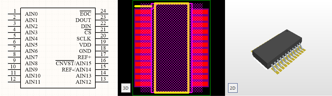
Components in your managed PCB library need to include more than just a schematic symbol. They should include:
- Schematic symbol
- PCB footprint
- Component information (detailed component description, manufacturer, manufacturer part number, key specs like voltage and current, datasheet link or file, simulation models, etc.)
- Storage location that everyone can access
This is your baseline. Any hardware design needs these for every component.
Step 2: Create Schematic Symbols In a Universal Way
For schematic symbols:
- Use IEC/IEEE standard symbols. Senior engineers can read your schematics faster. If you need to show the actual pin layout for debugging, make a second symbol version.
- Set pin types correctly. Don’t mark everything as “passive.” Use input, output, bidirectional, power as needed (refer to the datasheet). Correct pin types help DRC catch issues automatically.
- Add a detailed description. Write what the device does and where it’s used, e.g., “STM32F4 ARM Cortex-M4, 168 MHz, used for motor control in Products A, B, C.” Future you will thank you.
- Include a company internal part number. This lets you map multiple manufacturer part numbers to the same internal device.
- Store symbols where everyone can access them. Use a network drive with version control, cloud storage with built-in versioning, or Git/SVN.
- Use symbol and footprint previews if possible. Choose a system or PLM that lets you preview without downloading, or upload preview images of symbols, footprints, and 3D models.
Reminder: Pin mapping errors in PCB component libraries happen when the pins defined in the schematic symbol don't correctly correspond to the physical pads on the footprint. These are commonly caused by manual component creation mistakes, misreading datasheets, or copy-pasting and modifying existing components without a full audit.
The best prevention is a controlled, integrated component creation workflow that explicitly links symbol pins to footprint pads and requires verification against the datasheet before the component ever hits a library.
Step 3: Handle Footprints Without Overthinking
Footprints are easier than symbols. Follow these steps:
- Name them using IPC-7351. This gives you consistent, meaningful naming.
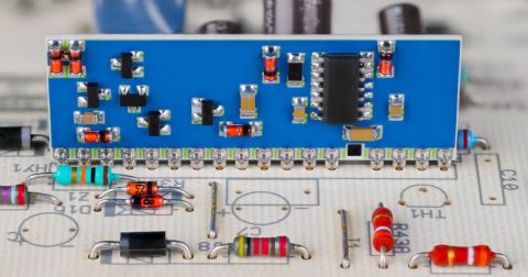
- Download a standard footprint starter pack. Get your common 0201, 0402, 0603, 0805, 1210, SOIC, SSOP, and other standard footprints from a trusted source (e.g., Octopart) in one go. This covers most parts you’ll use.
- For custom device models, download as needed. For connectors, inductors, and other unique parts, download footprints as needed, test them locally, then push them through your release process into the centralized hub.
- Include land patterns for different board densities. This is especially important for HDI PCBs and to match soldering methods used by your fabricators.
Step 4: Set Up Version Control
At one of my previous roles, a senior electrical engineer wasn’t consistently using version control. A few months into a project, the Director of Engineering spotted that a resistor had changed from 3 kΩ to 10 kΩ. He had a printed schematic from the week before showing the correct value.
The likely cause: an alternate circuit solution was copied into the new design and the resistor value was never changed back.
I’ve made similar mistakes with harness design details. The correct circuit, but two wire labels were wrong. In that case, a schematic backed up in SVN can be used to revert everything to the correct versions in minutes.
Whether you use Git, SVN, PLM, or a cloud solution, you need digital version control and a trackable approval process connected to your design software. Visual notes alone are not enough.
Step 5: The Approval Process
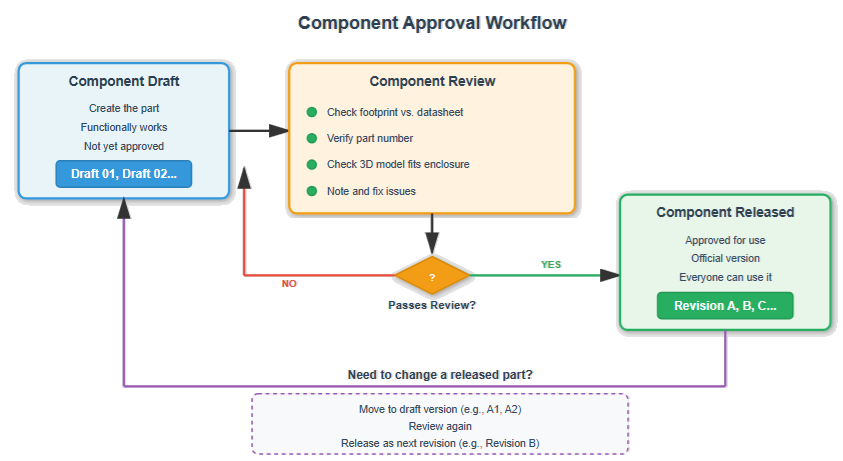
You can't use a part in production or prototype until it's been released. So here’s a simple approval workflow:
- Component Draft
- You make the part. It works functionally, but it’s not approved.
- Mark it Draft 01, Draft 02, etc.
- Component Review
- Someone checks the footprint against the datasheet.
- Someone verifies the part number.
- Someone checks that the 3D model fits in the enclosure.
- Issues are noted and fixed.
- Component Released
- Once it passes review, it becomes Revision A.
- Now everyone can use it. It’s official.
If you need to change a released part, move it back into a draft (e.g., A1), review again, then release it as Revision B.
Version numbering example:
- Draft 01, Draft 02, Draft 03…
- Approved → Released = Revision A
- Next change cycle → Draft → Review → Revision B
Rule: Always leave a clear comment explaining the key change you made. Not just “updated part,” but “Changed pin 7 type from unspecified to power because DRC was failing on Sheet 4.” Six months from now, someone will wonder why you changed it and might revert it. Comments prevent that.
Step 6: Who Reviews and Approves What
Having a standard approval process makes everything faster and more reliable.
Assign clear ownership:
- One senior engineer approves all analog parts.
- Another approves digital parts.
- Mechanical engineer checks 3D models and clearances.
- A director or lead gives final approval.
Put the owner’s name in the part info. When someone has a question about an STM32, they know exactly who to ask.
In companies with tens of thousands of components, it’s common to assign a significant portion of library management to one engineer and add more people as needed. PCB designers can then focus on layout, electronics engineers on circuits, and hardware engineers on system integration.
As your company grows, you can even have a full-time “library person.” Everything goes through them, which makes the library more consistent and predictable.
Where To Store Everything
You need one place to store all component models (PCB footprints, schematic symbols, 3D models, etc.). Not scattered across local laptops and random folders.
| Option | Description | Pros | Cons |
| Company Server | Shared network drive with Git/SVN for versioning | - Full control over data and infrastructure - No monthly cloud fees - Fast access on-site | - Remote access can be difficult - VPN issues and drive mapping hassles - You’re responsible for backups and maintenance |
| Cloud Storage | Centralized cloud environment for libraries | - Access from anywhere - No VPN issues- Automatic backups - Real-time synchronization | - Ongoing subscription costs - Requires internet connection - Less direct control over security unless you pay for higher tiers |
A common strategy: engineers work with a local copy of the component library, modify it, verify parts in real designs, then push updated components back to the central repository with version control. Working directly from a network drive is possible but can cause ECAD performance issues.
Pro Tip: Using a centralized library reduces errors by having the whole hardware design team pull data from the same approved source. This ensures that every engineer on your team is using the same approved component symbols and footprints.
What Core Capabilities Should a Centralized Component System Include?
Aim for the following functionalities:
- Preview parts without downloading. Huge time saver when reviewing components.
- Track all designs where a part is used. You need to know where a component lives across all products.
- Component status tracking: obsolete, out of stock, low stock, NRND. Having this before manufacturing quotes saves weeks of back-and-forth.
- Ability to update a component across the ecosystem. When you update a resistor footprint, that change should propagate or be easily pulled into all relevant designs.
- Comments and notes on parts. For example: “This chip runs hot, add heatsink (see datasheet page 47),” or “Only use this footprint with FR4.”
- The latest stock checks. Connect to distributor APIs or BOM tools to see availability before using parts.
If your centralized flow doesn’t support these, you’ll spend more time “babysitting” parts than designing boards.
Migrating Your Local Library Into a Centralized System
Migrating a local library to a centralized cloud system is less of an IT task and more of a component quality audit. Before moving anything, categorize your existing parts in a way that helps you prioritize what moves first. For example, by usage frequency, data completeness, or lifecycle status.
Before you move anything over you’ll need to do two things.
- You’ll then need to standardize on required component fields.
- You’ll need to set up a folder structure in your system.
Once these have been done, you can start to migrate your components. It can be a good idea to do this in batches starting with your highest-use parts, rather than all at once.
Your New Workflow For Every Part
Here's a suitable workflow for adding any new part to your centralized library:
- Find the part and check suppliers, prices, availability, and CAD models.
- Check if the part is in production or obsolete. Don’t use obsolete parts. Look for recommended alternates if needed.
- Check the package and PCB footprint. Ensure the package and footprint match in size and style.
- Get a 3D model. If not available in your main source, check the manufacturer’s website or dedicated 3D model libraries.
- Check stock and availability history. If the part is often out of stock, choose another part.
- Find alternate parts. Especially for ICs. Add reasonable alternates now, not when your primary part is 12 weeks out.
- Consolidate distributors. Prefer parts available from multiple suppliers with reasonable minimum order quantities.
- Download the component datasheet. Store it locally on company servers because URLs change.
- Save the component model and information to your shared library with version control.
- Add a brief comment on why you set up or changed the part. Then push changes.
Do this consistently and you’ll avoid many unpleasant surprises later.
Alternate Parts Matter More Than You Think
For alternate parts:
- List alternate part numbers in your part info.
- Note any circuit changes (different pinouts, specs, or tolerances).
- If possible, test both parts before releasing the design.
If you really can’t find an alternate because the part is uniquely suited:
- Make sure it’s widely available.
- Prefer a stable manufacturer.
- Ensure multiple distributors carry it.
- Be explicit that it’s a risk and document it.
When possible, also consider alternate circuit designs that achieve the same function with different parts. This becomes part of your design reuse library.
Component Library Maintenance
A practical update cadence:
- Weekly: Add new parts as teams need them (using the workflow above).
- Monthly: Update older libraries. Check for obsolete parts and decide how to handle them.
- Every six months: After successful product launches, add parts that performed better than original selections.
- Yearly: Refresh all components, especially ICs, to catch changes in manufacturers, acquisitions, and obsolescence.
During updates, ask:
- Are parts still in production?
- Are parts in stock at distributors?
- Are there newer or improved versions?
- Do any parts need alternates added?
- Are there better or cheaper options now?
If you use a part that went obsolete two years ago and only discover it at ordering time, you may face redesigns or risk buying from questionable vendors.
Connecting your centralized library to distributor data or availability databases lets you see when parts are running low before you commit to using them. Supply chain realities drive hardware schedules.
Access and Permissions
Once you have a solid system for component libraries, define access:
- All relevant electrical and electronics engineers need access to view and download parts.
- Certain mechanical engineers need access to 3D models and footprints to check fit in enclosures.
- ECAD and MCAD collaboration tools make this even more important, ideally with shared component dimensions and enclosure information.
A typical permission model:
- Everyone approved can view and download parts.
- Engineers can create draft parts.
- Designated reviewers approve parts.
- Leads/directors release parts.
When you’re lean, this may all fall on one or two engineers, but aim for multi-person review as soon as possible.
Frequently Asked Questions
How do enterprise PCB tools handle component library version control and access permissions across teams?
Enterprise tools centralize the component library so everyone pulls from the same verified source, with built in version control, so all changes are traceable and reversible. Access permissions then define who is able to view, edit, and release components.
Should mechanical, firmware, and electrical all share the same database?
Yes. If they’re touching the same product, they need the same information, especially with more integrated ECAD–MCAD workflows.
How do we prevent people from accidentally changing released parts?
Use proper permissions, version control, and approval workflows. Many centralized systems can lock released files. If yours can’t, enforce file permissions on your server.
What's the right schedule for library updates?
Add new parts weekly, do bulk updates monthly, perform post-project updates every six months, and do a full refresh yearly. You either pay the price now or pay more later.
Our contractor won't use our library. What do we do?
Understand their reasons, but ideally work with contractors willing to use your library or integrate theirs into your ecosystem.
How do we handle parts that are only available from one manufacturer?
Document it as a risk. If possible, create a backup circuit design and monitor stock closely.
Conclusion
Tom Hausherr once told me in a meeting: “A PCB layout is only as good as its component library.” Once you have a centralized library set up, you’ll wonder how you ever worked without it.
With a solid system in place, you can manage your PCB components, get up-to-date supply chain data, and access millions of ready-to-use parts, all in one secure PCB component library. If you want to put these best practices into action, experience what this looks like in practice with Altium Develop.

About Author
Related Resources
Related Technical Documentation
Table of Contents
- Key Takeaways
- What Happens When Everyone Does Their Own Thing
- How To Fix The Whack-a-Mole Parts Problem (Without Going Crazy)
- Step 1: Define Your Component Creation Workflow
- Step 2: Create Schematic Symbols In a Universal Way
- Step 3: Handle Footprints Without Overthinking
- Step 4: Set Up Version Control
- Step 5: The Approval Process
- Step 6: Who Reviews and Approves What
- Where To Store Everything
- What Core Capabilities Should a Centralized Component System Include?
- Migrating Your Local Library Into a Centralized System
- Your New Workflow For Every Part
- Alternate Parts Matter More Than You Think
- Component Library Maintenance
- Access and Permissions
- Frequently Asked Questions
- How do enterprise PCB tools handle component library version control and access permissions across teams?
- Should mechanical, firmware, and electrical all share the same database?
- How do we prevent people from accidentally changing released parts?
- What's the right schedule for library updates?
- Our contractor won't use our library. What do we do?
- How do we handle parts that are only available from one manufacturer?
- Conclusion
Smarter Workflows for ECAD Librarians
- Smarter Workflows for ECAD Librarians
- Spend less time preparing cloud components
- Easily maintain component libraries
Learn More
Thank you, you are now subscribed to updates.