


Defining PCB Library Types and Methodologies for Your Design Process

At a Glance
PCB design libraries need to be created and maintained by a design team. See how you can implement a PCB library creation process.


Every PCB layout and schematic is built on a single foundation: PCB libraries. A library contains all of the basic hard data a designer needs to create the circuitry and PCB layout for a new product. A well-maintained library is key to getting through a design process successfully while preventing many simple errors in fabrication and assembly. Everyone from individual designers to large companies can and should maintain PCB design libraries.
But as your experience grows and your library matures, what is the process that should be used to build and maintain it? Parts can go obsolete or change, original CAD data comes from a variety of sources, and not all designers have the time or resources to constantly monitor their PCB library data. We'll show you some tools and processes that help you build and maintain your PCB design libraries.
What's in a PCB Library?
It is not difficult to understand the information that goes into an ECAD library with PCB components. All libraries require a minimum viable amount of information to be usable in PCB design software:
- Schematic symbol for drawing the electrical connections
- PCB footprint representing the physical location where the components will be mounted
- A manufacturer part number for the components, or at minimum a description that allows the correct component to be purchased
Other information is often included to make the component representation more complete, most commonly a 3D model, followed by additional electrical parameters and simulation models.
In order to build a PCB library, you could have maximum control over your internal library standards and build all the components yourself. Some companies have a dedicated ECAD librarian team that handles these tasks. But what if you're a small team or an individual designer? What's the fastest way to start building out a PCB library and maintaining it over the life of a new project?
Finding the CAD Data For a PCB Library
Before implementing a build process for a PCB library, keep in mind there are resources available for finding symbols, footprints, and 3D models for components. Some of these options are convenient as they offer free component data which are oftentimes provided by the component manufacturer. You can then download from these resources and put the data into your library.
When I need to add a new component to a library or project, I'll look in one of the following places:
- Inside my existing libraries for reusable symbols and footprints
- On the manufacturer's website
- On a franchise distributor's website
- On Octopart.com
If you're only looking for a baseline set of components to start building a library, you can find PCB libraries on GitHub. Be careful with these libraries only because the level of input from other designers varies significantly. For this reason, there's always a risk that some symbols or footprints are incorrect, and the parts should be reviewed once they are selected for use in a project.
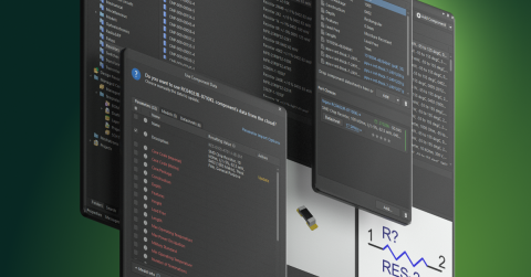
Altium users can find many components in the Manufacturer Part Search panel inside Altium Designer. Manufacturer Part Search panel allows you to search for components, and you can narrow down to components that already have available symbols and footprints. These can then be instantly imported into a schematic and used in a new project.

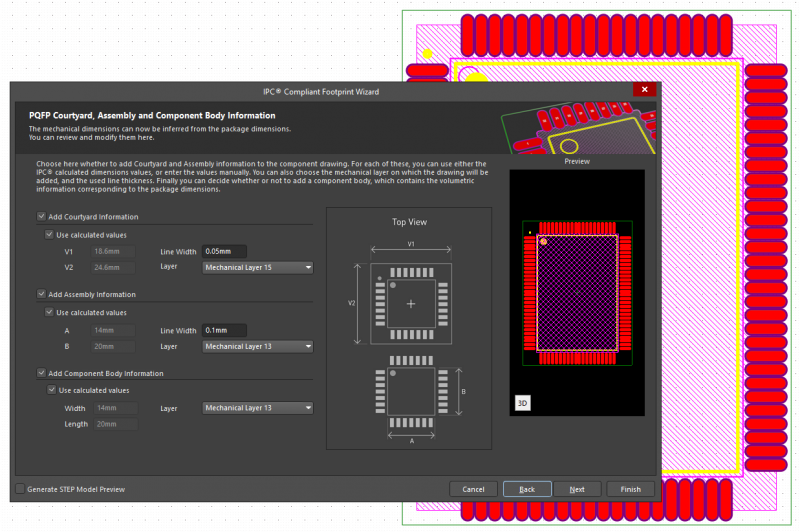
If you need to create a PCB footprint and generic 3D model from scratch, you can use the IPC Compliant Footprint Wizard and attach the new footprints to your symbol. The footprint generator will automatically create footprints and an associated 3D model for common package types based on pin count and pitch. It will also handle leadless components like QFNs and BGA packages. The rules for creating these models are based on IPC standards for surface mount and through-hole components.
For all other parts which have non-standard packaging, you will need to get the models from the component manufacturer if they are available, or you will need to create these on your own. Any parts that do not have pre-made models will need to be created and validated. The same validation steps should be applied to third-party components. This is often performed by the individual designer working on a project during the schematic capture phase as parts are identified and approved for use in a project.
When a user adds a draft part to a library, the part needs to go through some qualification process before being released to use in new projects. Different designers or companies may have different opinions on when is the right time to release a part for use in new designs. For example, I often wait until after a prototype is assembled to validate a library and start reusing the parts in new designs.
One example process for validating draft components is shown in the flowchart below.

In total, this covers the library creation side of the equation, but we still have two other ongoing tasks: library management and library maintenance.
How to Store and Catalog PCB Library Parts
PCB library parts are commonly stored in a file-based CAD database or through a company database. The method for doing storage and cataloging parts depends on how your company or design practice is structured. Larger companies tend to have a dedicated CAD group which maintains libraries, and designers are able to search for parts they need in new projects. An individual designer will need to maintain their own library files or database.
I have often talked about taking a file-based approach for specific clients rather than maintaining a single library for reuse in every project. However, you can still have a centralized library with all of your commonly used parts, and this is maintained across client projects. The centralized library approach is also aligned with processes at larger companies.

Project-Based Libraries
Project-based libraries are most suitable for freelance designers, contract engineering firms, and PCB design services companies who work with multiple clients. In this approach, designers maintain their own centralized master library for reference, but create individual project libraries as deliverables for each client engagement. When a project is completed, all CAD data used in that specific design is compiled into a single master project library that accompanies the native CAD files and manufacturing outputs.
This approach ensures clients receive a complete project archive with all necessary CAD data to regenerate the PCB file, even if they work with different design firms in the future. Note that the inputs to this final library can come from multiple sources, namely the designer's library, the client's library, or third-party sources. The project library serves as a standalone reference that can be stored and accessed independently.
Centralized Library
A centralized library approach involves maintaining a single master library with standardized components that are reused across multiple projects within a company or design practice. This method works best for OEMs, ODMs, manufacturers, and companies that produce their own products, as it ensures consistent CAD data and enforced standards across all design projects.
The centralized library is typically overseen by a dedicated person or team responsible for maintaining data quality, reviewing components, and managing updates. This approach eliminates redundancy and reduces the risk of errors by providing a single source of truth for all component data. Designers pull verified components directly from the centralized library into their projects, ensuring that symbols, footprints, and associated data remain consistent.
Which Type of Library is Best?
In summary, the centralized approach works for everyone, and tools like Library Migration in Altium 365 and the parts management features in the cloud-based library make it easy to maintain a single library with qualified parts. Engineering services companies who are designing for clients can still export project-based libraries for each design project.
Creating and exporting project-based libraries is only viable for an engineering services firm. This approach is also adaptable to cases where a client provides their own library and expects the designer to add components or make modifications. Of course, there is a risk of reinventing the wheel each time a project is created, so smart engineering firms will need some other way to catalog which parts have been used in past projects so that they can be candidates for reuse in new projects.
Learn more about these library approaches in this video on Altium Academy:
Maintaining Libraries
Once libraries are created, they need to be maintained in some way. Unfortunately, a library can grow so large that the library might be difficult to review on a regular schedule, so you have to pick and choose when certain parts of the library are reviewed and updated.
That being said, there are some opportune times to review and update components, even after they passed an initial review process:
- When a component reaches the end of its life cycle
- When an integrated circuit has a silicon or package revision
- A part number change occurs, which is typical for passives
- When an assembler flags a potential defect due to a footprint design
- When an assembly defect occurs repeatedly in volume production
- When an electrical defect is discovered during testing
- Mechanical interference with a specific component is discovered
These are not the only instances where a component review and data update may be required. But because the problems cited above often originate in the library, this would be the time to perform the review of the library data.
The problems with component life cycles are unpredictable, and you will not know a component will be phased out unless you read announcements from the component's manufacturer. Most designers or component buyers notice an obsolete part once they submit an order for it from a franchise distributor.
But with the managed libraries in Altium 365 and the Supplier Links feature in Altium Designer, users can see low inventory and late life cycle issues with parts before a design is completed and finalized. Even if you do not use these features, the Active BOM feature in Altium Designer will show late life cycle and out-of-stock parts before sending your BOM off for quote. The best way to ensure product development and production stay on schedule is to get ahead of the situations before starting production.

Whether you need to build reliable power electronics or advanced digital systems, use Altium’s complete set of PCB design features and world-class CAD tools. Altium provides the world’s premier electronic product development platform, complete with the industry’s best PCB design tools and cross-disciplinary collaboration features for advanced design teams. Contact an expert at Altium today!

About Author
Related Resources
Related Technical Documentation
Table of Contents
Design to Release, Without the Friction
- Keep reviews tied to the right version
- Reduce handoff confusion and rework
- Spot sourcing and release risk earlier
- Work solo, share when needed
Get Started
Thank you, you are now subscribed to updates.


