


How to Manage ECAD Libraries for Consistent PCB Layout Design

At a Glance
Set up ECAD libraries that scale so your PCB layouts are consistent, traceable, and first-time-right.


Nothing hurts more than doing everything right in a hardware design, only for your board to fail because of a single footprint. I’ve been through this, so don’t repeat my mistakes. Learn how to manage ECAD libraries for consistent PCB layout design.
Key Takeaways
- A single mismatched footprint can cost weeks of delay, $20,000 in lost production, and a client relationship. Even minor oversights can destroy trust and schedules.
- Disorganization and missing structure in ECAD libraries are among the top causes of PCB failure. Standardized processes and component data are essential.
- A strong component description is more valuable than a part number because it ensures traceability, simplifies replacement, and prevents costly redesigns when parts go obsolete.
- Reliable PCB design depends on five pillars: schematic symbols, component data, simulation, 3D models, and land pattern.
- Simulation, 3D collision checks, and IPC-compliant footprints prevent downstream errors that are expensive or impossible to fix post-fabrication.
- A disciplined library management system turns chaos into reliability. Process doesn’t slow you down. Mistakes do.
The $20K Footprint
Early in my freelance career, I was moving fast, eager to prove myself to a new client. The design was complete, fabrication went smoothly, and all the parts were in stock. Two weeks later, as assembly began, I got an email that made my stomach drop: “Production pause – PCB component cannot be placed in assembly.”
I was convinced it had to be a part number issue. I checked the BOM, the schematic, and the board layout. Everything looked fine. Until it didn’t.
One footprint had the wrong pinout. I’d swapped it mid-design for a test and forgot to sync it back to the schematic. That one small oversight halted production.
The result? $332 wasted on five test boards, a six-week delay, and a lost $20k production run. The client’s trust – gone. They missed their deadline and chose another designer for layout work. The colleague who had referred me stayed polite, but I never got another project from that company.
It was brutal, but also the most important lesson of my career. Even the best engineers make mistakes when they lack structure. I had no checklist, no standardization, just what was in my head. That had to change.
Here’s the core principle I learned:
Keep the minimum essential data for every part in your library. For buyers, the most important field is the Manufacturer Part Number (MPN). But for designers, it’s the component description.
Why? Because MPNs only matter when buying parts, and they age fast. I learned the hard way that after just a few years, you can lose access to part info, suppliers, or even the manufacturer. Without a description, you need to decode the old schematics to determine what the part was, or worse, redesign that section of the board.
A detailed component description acts as a safeguard. It summarizes the datasheet, defines key characteristics, and lets you quickly find equivalent, active parts across suppliers. That’s why experienced engineers always save datasheets, even for capacitors. They know parts will go obsolete, and time spent hunting down replacements is productivity lost.
So no, it shouldn’t be “normal” to spend half your time searching for part information. That’s why I now rely on BOM management tools and a standardized process to keep every component traceable, replaceable, and ready for production. In the next section, I’ll walk through that system, the one that made sure I never lost a client over disorganization again.
You might think, “We’re small; a process will slow us down.” I thought that too. But as my story shows, even a one-person team can miss something when you don’t respect your own process, only discovered weeks later during assembly.
One footprint can wreck a schedule. If a part can’t be placed, assembly stops. Then you’re hand-soldering, brutal on a high-density board.
I’m sharing the internal process I kept in my head so you don’t repeat my mistakes or cost your client. You can’t wait to “grow into” process. Smaller teams have less buffer. A bit of rigor per part saves weeks of work, tens of thousands of dollars, and protects future sales, cash flow, and the company.
Process doesn’t slow you down. Mistakes do.
So what’s the takeaway? Maintain a detailed component description so the part can be recreated far into the future, and double- or even quadruple-check footprints.
Why Do Part Libraries Break Entire Product Launches?
The most common issues with part libraries are the following:
MPN-Only Records (with No Descriptive Fields)
What really hurts is when a record has only a manufacturer part number and nothing to identify the part.
MPNs go obsolete, and not all manufacturers will keep obsolescence records of old MPNs. Companies also get acquired and the old records get lost over time, especially on long-lifetime products like aerospace systems. When all you have is a part number, the info that was online for years may suddenly disappear today.
Single-Supplier BOMs, Lifecycle Blind Spots
Last week, I submitted a BOM for a client. Layout and Gerber checks were fine, but parts weren’t in stock, some were understocked (<1–2k units), and there were no backup suppliers. On older designs, engineers had eight-plus sources and alternates. Everything ran smoothly.
Buyers often need to rely on more than one source, which means engineers need to provide alternate supplier options in the BOM. Otherwise, assembly gets delayed and the designer needs to spend extra time looking through distributor websites to find inventory.

The Framework: The 5 Pillars of a Solid Component
Now that it’s clear a perfect PCB library is essential, how do we prevent these problems? Here’s a robust framework to use in hardware design and production. There are five key elements every device/component must have in your parts library. Burn these into your database and never skip them. Add anything else you want, but always include these.
In ECAD libraries, we model the digital equivalent of that physical device in our design software. To do that properly, we must show:
Product properties
- Information about the part: availability, price, minimum order quantity, description, and more.
- Electrical functionality: Simulation models (like SPICE, IBIS, etc) to predict behavior under different conditions before spending money on builds and tests. Often skipped in rushed cycles when hand calculations and datasheets seem sufficient.
- 3D model: A 3D representation of the device showing height, size, and shape, which is important for showing placement of the PCB in an enclosure.
- PCB interface: The area on the PCB where the part sits, the PCB footprint, to match the real physical part.
Pillar 1 - Schematic Symbol
A schematic symbol is the conceptual representation of a part. It conveys how the part works, including pins, pin names, and standard symbol conventions.
Correct visual representation matters, so don’t use generic boxes. For example, for a resistor, use a proper resistor symbol, not a box.
Pillar 2 - Component Information
This is the most important part of any device because it defines everything else. Without part data, you can’t buy it or build it. Each part needs the following information:
Component Description
This identifies the part in your database and is the fastest way to provide broad searchability based on specs. Using only the manufacturer part number for the component description isn’t practical because it doesn’t allow search by specification. A shorthand description with a few key specifications is better. Example: instead of LTST-C193TBKT-5A, use LED BLUE CLEAR CHIP SMD.
But let’s take it even further. Here’s my naming convention:
Long form (canonical):
LED BLUE 470NM CLEAR INDICATION DISCRETE 2.8V 0603 (1608 METRIC) SMD
Medium (ERP-friendly):
LED BLUE 470NM CLEAR 2.8V 0603 (1608 METRIC)
Ultra-short (label/line item):
LED BLUE 470NM 0603
I would go with option 2, the Medium (ERP-friendly) version.
Component Description
A component description includes function, key params, and package type. A “simple LED” isn’t just simple. Capture these details so it’s identifiable and usable.
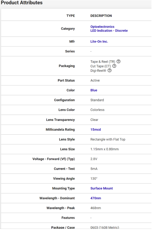
Accurate part descriptions make informed swaps possible. For an LED, you need data like forward voltage/current and brightness (mcd rating). A name like “LED BLUE CLEAR CHIP SMD” works as a part name, but not as a full description. It won’t help you find a replacement without a datasheet.
A better description is: “Blue 470nm LED Indication – Discrete 2.8V 0603 (1608 Metric).” It includes the forward voltage directly, wavelength, and package size, which is enough information to locate a similar part quickly through a simple keyword search.
Compare that to a poor description like “Blue LED SMD.” It tells you nothing about the forward voltage, luminosity, precise footprint, etc. That forces you to open the datasheet for this MPN, locate the basic electrical specs, and compare that against the engineering requirements or the design in the schematic. 30 minutes for one LED. Scale that to 40 parts in a 200 line item BOM, and the wasted hours (and cost) are obvious.
Datasheet
The only thing more valuable than the part description is the datasheet. Save datasheets for every part you use because manufacturers change links frequently. Keep a local copy and link it to the device, and also store the web portal link as a part field.
Think of the hierarchy this way:
- Component name: highest-level shorthand to find the part.
- Detailed description: one level down; succinct abstraction of the datasheet.
- Datasheet: source of truth.
The part name’s purpose is to help you drill down to what you need. It may or may not be enough to swap or recreate parts. When the description contains enough detail to find a new part, even better.
Manufacturer Part Number
The manufacturer part number is mandatory, even if you have a description for the part. Some manufacturers use similar part numbers or generic part number families (e.g., 7400 series logic, LM3xx series components, etc.), so the part number needs to be exact as it corresponds to a specific package, footprint, and electrical specifications.
Manufacturer Name
To avoid any confusion when searching for parts, it is important to have the correct manufacturer name at all times. This is also helpful if you plan to order some parts directly from the manufacturer’s website.
Suppliers
It is a good idea to list at least one supplier. Most manufacturers sell via franchise distributors (e.g., Digi-Key, Mouser, Avnet, Newark). Use Octopart to see available suppliers and delivery options to your door or assembly house.
Pillar 3 - Simulation (When Needed)
When real-time performance matters and you need a first-time-right design, circuit-level and layout simulation provide a good comparison for test results and help catch simple problems early.
So what can we do to simulate our parts?
- SPICE models, for basic circuit operation, failure analysis, especially in power electronics.
- IBIS models, for high-speed simulation and analysis to detect impedance problems in advance. Use for rise times and board frequencies around 1 GHz and above. Practically mandatory for high-speed digital (DDR, PCIe Gen 3/4/5, USB 3.2). For anything near ~10 GT/s and higher, simulate with IBIS to validate before testing. Keep in mind that results can vary with the PCB’s dielectric material.
Pillar 4 - 3D/MCAD Model
Many products have tight clearances in mechanical enclosures, so every millimeter in X, Y, and Z matters. Using 3D collision check against the enclosure, an interference issue can be located before building any prototype assemblies.
Even in 2021, it wasn’t uncommon to work with footprints only, but if you’re going to production, include 3D models and run collision tests. If the part can’t be placed on the PCB, you don’t have a product. The part exists beyond the PCB. Typical 3D formats are STEP (AP224, AP214, etc.). Collect those models and keep them organized.
Pillar 5 - Land Pattern on the PCB
We need to place the part onto the PCB. The land pattern defines the copper pads where the component will be soldered. There’s the manufacturer’s recommended land pattern, and there’s the realistic land pattern that depends on PCB layout density as defined in IPC standards. Options like Least, Nominal, and Most material conditions in IPC-7351/7352 are intended to balance part-to-part pin spacing against the need to form a sufficiently large solder fillet.
Given its importance, here’s what I always check for footprints.
PCB Footprint Checklist
- Pin-1 polarity
- Paste reduction % noted (0% is standard nowadays. The fabricator will change it)
- Courtyard
- Pad dimensions called out (saves every engineer from having to do it manually each time)
- Most/Nominal/Least rationale
- Keepout regions
There are more checks to do, but these are the most important. You don’t want to discover during layout that a part leaves too little space on a high-density PCB. You’ll have to change it or find the correct footprint or part anyway. Do the work now, or do twice the work later.
Closing and a Strong Recommendation
“A PCB design is only as good as its CAD library.” That’s what I remember from my meeting with Tom Hausherr during the December 2021 holiday downtime, as he shared war stories from leading IPC-7351 updates.
The takeaway was clear: components dictate PCB success. Every irreparable failure I’ve had traced back to a component oversight. With the right parts, a flawed circuit can often be adjusted, but not the devices themselves. And after fabrication, finding a footprint-compatible replacement is a gamble, not to mention the time lost desoldering and reworking instead of testing.
Whether you need to build reliable power electronics or advanced digital systems, Altium Develop unites every discipline into one collaborative force. Free from silos. Free from limits. It’s where engineers, designers, and innovators work as one to co-create without constraints. Experience Altium Develop today!

About Author
Related Resources
Related Technical Documentation
Table of Contents
- Key Takeaways
- The $20K Footprint
- Why Do Part Libraries Break Entire Product Launches?
- MPN-Only Records (with No Descriptive Fields)
- Single-Supplier BOMs, Lifecycle Blind Spots
- The Framework: The 5 Pillars of a Solid Component
- Product properties
- Pillar 1 - Schematic Symbol
- Pillar 2 - Component Information
- Pillar 3 - Simulation (When Needed)
- Pillar 4 - 3D/MCAD Model
- Pillar 5 - Land Pattern on the PCB
- Closing and a Strong Recommendation
Design to Release, Without the Friction
- Keep reviews tied to the right version
- Reduce handoff confusion and rework
- Spot sourcing and release risk earlier
- Work solo, share when needed
Get Started
Thank you, you are now subscribed to updates.