



Collaborative Engineering: The Power of Accuracy with Team Ribbot

At a Glance
Through the story of Team Ribbot, a combat robot built for the BattleBots Pro League, we see firsthand how even a small mishap in translation can lead to costly redesigns and missed deadlines. By utilizing MCAD CoDesigner for direct synchronization between ECAD and MCAD, teams can maintain data integrity, preserve design intelligence, and eliminate translation errors, ensuring that every millimeter counts.


In high-performance hardware, a single millimeter decides whether a part fits or fails. Yet the traditional way of moving a design between electrical and mechanical tools makes that millimeter hard to trust. Neutral interchange files such as STEP, DXF, and IDF have to translate a design from one application's language into a generic format, then back again on the other side. Every translation flattens geometry and rounds coordinates. A small conversion error at the start becomes a fit failure at the end.
- Neutral files such as STEP and IDF strip the intelligence out of a design, leaving disconnected geometry that has to be repaired by hand.
- The dangerous errors are the small ones. A fraction-of-a-millimeter shift passes unnoticed and corrupts everything built on top of it.
- MCAD CoDesigner transfers data natively in both directions, with no intermediate file, so there is no conversion step to introduce error.
- Native transfer preserves design intelligence, not just shape. Component designators and part numbers stay linked across the electrical and mechanical worlds.
The Ribbot Case: When Millimeters Matter
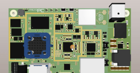
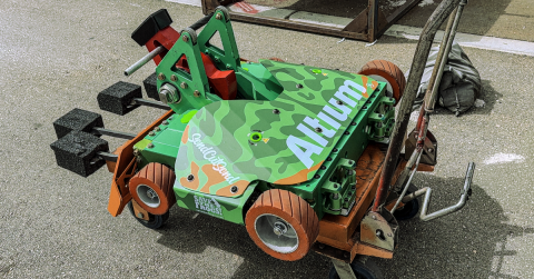
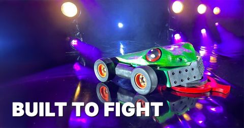
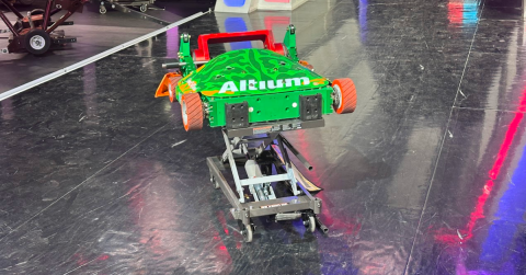
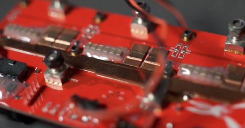
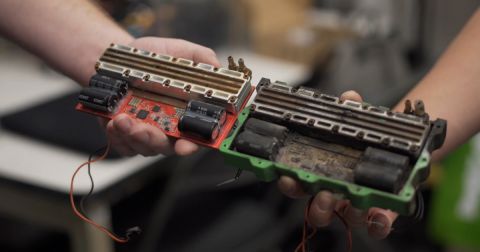
Ribbot is a 250-pound combat robot built for the BattleBots Pro League. Its custom motor controllers have to be accurate to the millimeter. The board carries critical components on both sides, mechanical features for electrical connections, and mounting holes that hold a heat sink against the FETs under real preload.

At that density, a translation error is not a rounding footnote. A pin location shifted by a fraction of a millimeter during a file conversion means the board no longer seats in the machined aluminum housing. For a team competing at the top of the league, on a tight timeline and a limited budget, a single bad transfer can mean an enclosure that has to be redesigned from scratch. The safest path was to remove third-party files from the process entirely.
The Flaw of Neutral Files
The weakness in the conventional workflow is the neutral exchange file itself. STEP and IDF formats remove the intelligence from a model and turn a structured design into a set of disconnected shapes.
The large errors are not the threat. A wrong origin or a flipped axis is obvious, and someone catches it fast. The real danger is the microscopic mistake. A one-millimeter rounding error on import is invisible to the eye. It slips through, and the engineer keeps building on a foundation that is already wrong. By the time the error surfaces, fixing it costs far more than catching it would have.
Old Workflow: The Export-Import Roulette
In previous years, the electrical engineer exported an IDF file, compressed it, and emailed it to the mechanical engineer, who imported it and hoped the data had survived the trip.
Every transfer meant manual repair. Neutral formats lose constraints and distort curves, so engineers had to rebuild splines, realign mounting holes, and redo assembly mates before they could work. They were not designing. They were patching data and working around the limits of the format. One missed flaw could cascade into a full enclosure redesign when nothing fit at assembly.
New Workflow: Native, Direct Synchronization
Ribbot removed the format error from the process by using the direct synchronization in MCAD CoDesigner. Instead of generating an external file, CoDesigner moves the design between Altium Designer and the mechanical CAD tool natively. It maps the data structure of the board design directly into the native format of the mechanical assembly. With no conversion step, there is no conversion error.
When the electrical team places a dense connector, the mechanical team receives an exact geometric representation, unchanged. The direct link lets the team work through tight mounting positions and high component density without corrupting the data underneath. As Tim put it, the team is no longer dealing with stray exported solid files that could feed a mistake into the mechanical design or bad inputs into the electrical design.
One High-Fidelity Model, Trusted by Both Sides
The result is a single source of truth that both domains can rely on. Nick describes a high-fidelity model in both ECAD and MCAD that gives either engineer confidence the mechanical and electrical design will work together in place. That confidence is what let the team use rapid processes like 3D printing to check board-in-housing fit before committing money to machined metal parts. When the robot came together for the first time, everything fit. No surprises.
"The ability to see the components in 3D and know exactly how they are going to sit in the chassis is a game-changer. We don't have to worry about something hitting a wall or a support beam because we've already seen it in the high fidelity model." — Cam Collins, Principal Mechanical Engineer
How Native Synchronization Helps
MCAD CoDesigner bridges Altium Designer and leading MCAD tools, including SOLIDWORKS, PTC Creo, and Autodesk Inventor, without an intermediate file. Two things follow from that:
- Geometry survives intact. Complex board outlines, curved cutouts, and the mathematical description of splines and arcs transfer accurately, rather than being approximated into straight segments the way STEP or DXF exports often are.
- Intelligence survives too. The transfer preserves more than shape. Component designators and part numbers stay connected across the electrical and mechanical environments, so a change to one component updates its counterpart without breaking the link between them.
For a team designing non-rectangular boards inside enclosures that use every available cubic millimeter, that accuracy is the difference between a part that drops into place and one that has to be rebuilt.
No Data Loss Between ECAD and MCAD (Step-by-Step)
Winning on the Last Millimeter
In the BattleBots Pro League, mechanical and electrical systems have to work in perfect harmony, and harmony depends on data that does not drift in transit. By replacing the export-import round-trip with direct, format-free synchronization, Ribbot keeps its design data accurate from the first connection to the final build.
Keep your engineering data free of translation errors. See how accurate bidirectional synchronization works in MCAD CoDesigner.
Design Accuracy and Data Integrity: Frequently Asked Questions
Why are formats like STEP or IDF prone to losing accuracy during transfers?
These formats act as interpreters between different CAD applications. Exporting converts the native model into a generic geometric representation, and importing reinterprets that generic data into the receiving tool's native format. Round-off errors, parameter loss, and broken constraints happen along the way.
Does bypassing intermediate files mean we stop hunting for the right file version?
Yes. Because synchronization runs through the cloud, there is no "board_v4_final_updated.STEP" to track down. The data exchange manages changes natively, so the team works from current data instead of guessing which file is correct.
Are complex geometric elements like curved board cutouts preserved accurately?
Yes, and with better accuracy than neutral formats provide. STEP and DXF often approximate complex curves as a series of straight segments, which reduces precision. Direct synchronization keeps the mathematical description of splines and arcs exact.
What happens to component properties and designators without neutral formats?
They are preserved. Neutral files typically drop the electrical intelligence and hand over only a generic 3D body. Native synchronization keeps the link between the electrical data, such as designators and part numbers, and the mechanical design.
Related Resources
Related Technical Documentation
Table of Contents
- The Ribbot Case: When Millimeters Matter
- The Flaw of Neutral Files
- Old Workflow: The Export-Import Roulette
- New Workflow: Native, Direct Synchronization
- One High-Fidelity Model, Trusted by Both Sides
- How Native Synchronization Helps
- No Data Loss Between ECAD and MCAD (Step-by-Step)
- Winning on the Last Millimeter
- Design Accuracy and Data Integrity: Frequently Asked Questions
- Why are formats like STEP or IDF prone to losing accuracy during transfers?
- Does bypassing intermediate files mean we stop hunting for the right file version?
- Are complex geometric elements like curved board cutouts preserved accurately?
- What happens to component properties and designators without neutral formats?
Solutions for Every Role and Team
- Discover and evaluate design options earlier
- Develop in one shared workspace
- Scale with control and compliance
- Connect every stage of hardware development
Learn More
Thank you, you are now subscribed to updates.