


Seamless Mechanical Integration Using ECAD-MCAD CoDesigner

At a Glance
See how MCAD CoDesigner enables enhanced electromechanical design. Easily make quick, native changes, optimize fit checks, improve design visibility & more.


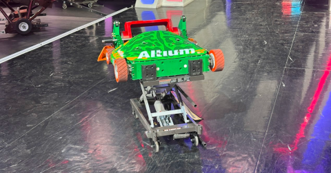
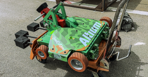
I’m excited to highlight some of the fantastic benefits of ECAD-MCAD CoDesigner and how it can be an extremely useful tool for tightly coupled electromechanical designs. Get ready to learn about why Altium MCAD CoDesigner is such an important part of what makes Ribbot successful!
Quick, Native Changes with Altium MCAD CoDesigner
Altium MCAD CoDesigner allows mechanical engineers to make changes to electromechanical designs in their native CAD tool, using the same commands that they use for 3D modeling on an everyday basis. This means that if changes are needed based on customer requirements or if an update is necessitated by the ECAD engineer to address fitment or routing concerns, these changes can be made quickly and natively. Altium MCAD Codesigner includes an integrated toolbar for creating keep-out areas. Instead of having to name a sketch or feature a specific reference identifier, Altium MCAD CoDesigner recognizes the keepout area automatically.
Optimize Fit Checks
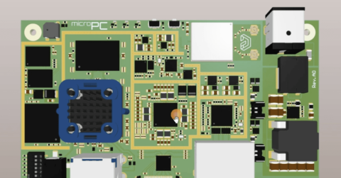
Performing a fit check of the final PCBA design is a critical function of the mechanical engineer. When importing an IDF file, many CAD tools will represent a circuit board as a green outline with various rectangles mounted on it. While this can be useful for checking component height clearances and interferences with the mechanical enclosure, this may not address all concerns.
Altium MCAD CoDesigner allows SMT components to be imported into the PCBA design with as much fidelity as is mandated by the user; if you want to generate a series of rectangles for fear of a large assembly file, you can certainly do that. If you want to import full CAD models, including solder fillets, you can achieve that level of realism. This means that you can see if that tall rectangle is a 1210 capacitor with leads that could short to the cover or a PEM with a non-conductive top surface.
Enhance Design Visibility
Altium MCAD CoDesigner stands apart from other tools by importing a decal of the primary and secondary side-board surfaces. This means that the external etch, solder mask, and silkscreen are all visible within the native MCAD domain. This is a huge innovation, as it allows a significant level of detail to be perceived with the MCAD model without making the file size exorbitant. This might instigate some cross-functional conversations; are we back drilling hot vias? Are we removing the solder mask in a specific area? Where are the test points, and are they accessible? The details of the decals are so good that you may even be able to spot footprint issues relating to insufficient heel and toe fillets. Unless you take the time to review the native board file carefully, these are cross-functional issues that may not be raised at design reviews.
Master Complex Circuit Board Designs
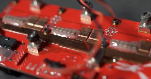
In today’s world of custom electronics, it can be difficult to find circuit boards with a simple outline. Perhaps the only exception may be the motherboard of the computer you’re using to access this blog. Many circuit board designs in the industry are designed for custom applications, with complex outlines and intricate cover designs to address environmental factors. Performing fit checks and ensuring that the electromechanical design will function as intended is critical. Altium MCAD CoDesigner provides mechanical engineers with surety that the board will fit and that the electromechanical design of the product is seamless.
Whether you need to build reliable power electronics or advanced digital systems, Altium Develop unites every discipline into one collaborative force. Free from silos. Free from limits. It’s where engineers, designers, and innovators work as one to co-create without constraints. Experience Altium Develop today!

About Author
Related Resources
Related Technical Documentation
Table of Contents
Design to Release, Without the Friction
- Keep reviews tied to the right version
- Reduce handoff confusion and rework
- Spot sourcing and release risk earlier
- Work solo, share when needed
Get Started
Thank you, you are now subscribed to updates.


