


Embedded System Implementation and Testing Before Commission

At a Glance
Embedded systems and PCBs in these systems need to be thoroughly tested before deployment.


Whether or not we want to admit it, most designs that are deployed in the field are embedded systems. They may not run a full Linux operating system, and they may not have huge processors or FPGAs, but they still execute some code in order to provide their core functionality to the end user. When you look at the higher value end of the electronics landscape, such as military and aerospace, the increase in embedded systems deployments over time is staggering. In addition to very aggressive form factors in the design, these systems need to be highly reliable and thoroughly tested.
The testing issue in embedded systems obviously revolves around core functionality, but there are also major reliability concerns for today's embedded systems. In this article, I'll run over some of the approaches to embedded systems testing, specifically with respect to power, functional testing, and thermal reliability.
Embedded Systems Functional Testing
The core functional testing for your embedded system needs to happen in code and physically by looking at the PCB. If you designed the initial prototype using a design for testability (DFT) approach, it will be much easier to qualify systems quickly and identify problems if they are present.
In another article, we've outlined some approaches that can be implemented in code to help validate embedded systems from a functional perspective. This involves code indicators and error flags, but that's not the only way to approach the physical design for functional testing. In most cases, you need to put the design on a bench and monitor both code and signal/power on the bench.
|
|
|
| Power monitoring |
|
| Signal monitoring |
|
| Test cases in code |
|
Any of these approaches can help you speed up some of the core functional testing while also monitoring power and signal. These kinds of test benches can get quite complex as you will have multiple instruments running at once with your test system.
Thermal Reliability
The other aspect of embedded systems that is quite difficult, especially in high reliability systems, is thermal reliability. Embedded systems can use a lot of power and thus generate a lot of heat, and so they need to be qualified thermally. The top-level goal is to ensure they can operate within spec and that they do not shut down due to thermal overstress. For thermal testing, consider which of these specifications apply:
- Is there an internal temperature limit in your enclosure?
- Is there a case enclosure touch temperature limit?
- Are there specific component temperature limits, such as certain sensors?
- Is there an attempt to maintain a thermal spec using only passive cooling?
All of these points will dictate where and how you measure temperature in the system while it operates.
Temperature measurements in an embedded system during operation are rather straightforward. For the individual designer without a huge budget, you can learn a lot about your embedded system just using the type K thermocouple that comes packaged with a multimeter. This will give point temperature measurements in the design. If you have multiple meters, use the prepackaged thermocouple and attach these to specific points where temperature measurements are most important. These points can be your main processor, main power regulators, the enclosure itself, or the air inside the enclosure.

Type K thermocouple
Set these up and let the system run as it comes to its equilibrium temperature. Depending on the size and cooling mechanism in the system, the time required for the system to reach its equilibrium temperature could be quite long. You'll have to set your meters up and leave them running for some time while monitoring your other instruments.
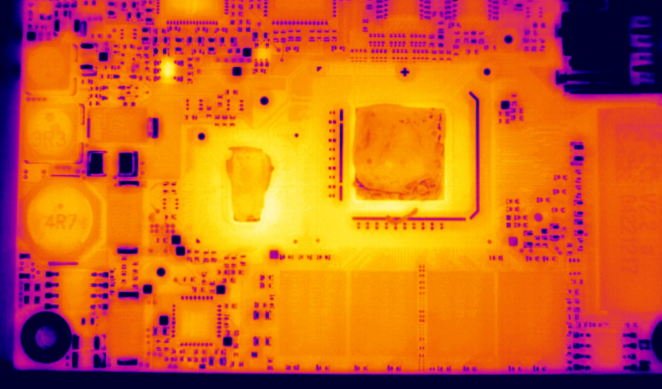
Once the temperature distribution reaches equilibrium, consider using a thermal camera to get the temperature distribution during operation. I think it's important to do this on the enclosure, especially if the enclosure has a touch temperature requirement. If your embedded system has built-in power supply, those enclosures can get very hot, and the user will not be able to touch or handle the system if active or passive cooling is not implemented directly on the enclosure.
If you are having a problem with excess heat in the design, take the PCB out of the enclosure and measure the temperature distribution directly with a thermal camera. If you take some images with a camera, you will be able to see directly where the hottest components are and what temperatures they will reach. This is very important as it will inform the cooling strategy going forward.
If your enclosure is creating an oven effect due to hot components, then enclosure or cooling strategy redesign may be necessary. Read the linked article below to learn about some enclosure design strategies that can help keep an embedded system cool.
Teams that need to collaborate on complex products can access a complete set of collaborative design features when using Altium Designer®. All stakeholders involved in product design can access a complete set of tools for PCB design that can support embedded development tasks, as well as cable and harness design features. When you’ve finished your design, and you want to release files to your manufacturer, the Altium 365™ platform makes it easy to collaborate and share your projects.
We have only scratched the surface of what’s possible with Altium Designer on Altium 365. Start your free trial of Altium Designer + Altium 365 today.

About Author
Related Resources
Table of Contents
Design to Release, Without the Friction
- Keep reviews tied to the right version
- Reduce handoff confusion and rework
- Spot sourcing and release risk earlier
- Work solo, share when needed
Get Started
Thank you, you are now subscribed to updates.

