


What Is An Oscillator? Everything You Need to Know

At a Glance
What is an oscillator? Mark Harris gives an in depth overview of the major categories of Oscillators. He explains the different types with their functions and drawbacks. Read more here.


Virtually every printed circuit board made in recent history has an oscillator of some form on it, and most integrated circuits contain oscillators too. You may be wondering, just what is an oscillator? Oscillators are essential components that produce a periodic electronic signal, typically a sine wave or square wave. Oscillators convert DC signal to periodic AC signals which can be used to set frequency, be used for audio applications, or used as a clock signal. All microcontrollers and microprocessors require an oscillator to set the clock signal in order to function. Some devices have them built-in, and some require an external oscillator - or both, having a low accuracy internal oscillator with the option for an external signal to be provided.
Electronic devices use the clock signal as a reference for time, allowing actions to be performed consistently. Other devices use the oscillator’s signal to generate other frequencies which can provide audio functions or generate radio signals.
Understanding different types of oscillators and how they function can allow you to choose the correct oscillator for your project. If you are trying to create a radio signal, you will need a much more accurate oscillator than you might need for other devices. Oscillators are something that can be easily overlooked in a project, with the attitude to simply grab any old oscillator that is within the frequency range specified in the datasheet that suits board space and cost requirements. There can be substantially more to the choice; however, depending on power requirements for the PCB, board real estate and the frequency precision that is required. Some oscillators operate on microamps or less power, where some need several amps to operate.
Oscillators fall into two major categories: Harmonic and relaxation. Harmonic oscillators create a sinusoidal waveform, RC, LC, tank circuits, ceramic resonators, and crystal oscillators all fall into this category.
In this article, we’re going to look at:
- Resistor-Capacitor Oscillators (RC)
- Inductor-Capacitor Oscillators (LC)
- Ceramic Resonators
- Quartz Oscillators
- Crystal Oscillator Modules
- MEMS Oscillators
- Silicone Oscillators
While you may not be looking to build an RC or LC oscillator yourself, and are instead reading this article for information about packaged oscillators that you can simply add to a circuit - I’m going to start out talking about RC and LC oscillators. It’s essential to understand how they function, and what their drawbacks can be, as many ICs with integrated oscillators use an RC or LC circuit.
By understanding how they function, you can better understand when it’s appropriate to use the integrated oscillator, and when it’s appropriate to add an external clock source. If you’re looking to learn more about the oscillators and clocks, you can easily build an RC or LC oscillator on a breadboard and test it with an oscilloscope. Before we dive into that, let’s take a quick look at a comparison between each oscillator type.
Performance Comparison for Oscillators
It’s worth noting for the table below that each option has a vast variety of different devices available on the market. When looking at fixed frequency MEMS oscillators, for example, options that are regularly stocked at DigiKey vary between 150 parts per million to 50 parts per billion in terms of frequency stability. This huge range of frequency stability also comes with a huge range of prices, so where one oscillator type might have options for extremely high stability or precision over a wide temperature range, it doesn’t mean that another option might not be cheaper for your precision requirements.
As an extreme example of this, the Connor-Winfield OX200-SC-010.0M 10MHz VCOCXO is a crystal oscillator that has a frequency stability of just +/- 1.5 parts per billion. The IQD Frequency Products LFRBXO059244BULK 10MHz atomic oscillator is over ten times the price in single-unit quantities for the same +/- 1.5ppb frequency stability. Despite this, there are going to be times where the $2000 atomic oscillator is going to be the superior choice for an extremely precise oscillator. IQD Frequency Products also make a VCOCXO that has a frequency stability of a mind-blowing +/- 1ppb over a wider temperature range than the atomic oscillator. At less than twice the price of the Connor-Winfield device in single quantity volumes, and still less than ten times cheaper than the atomic option. It’s incredible to me that we can have atomic clock sources readily sourceable today, and even more crazy that we can have a crystal oscillator that is more precise for a fraction of the price.
|
Clock Source |
Frequency |
Accuracy |
Advantages |
Disadvantages |
|
Quartz Crystal |
10 kHz to 100 MHz |
Medium to High |
Low Cost |
Sensitive to EMI, vibration and humidity. |
|
Crystal Oscillator Module |
10 kHz to 100 MHz |
Medium to Extreme |
Insensitive to EMI and Humidity. No additional components or matching issues |
High cost, high power consumption, sensitive to vibration, large packaging |
|
Ceramic Resonator |
100 kHz to 10 MHz |
Medium |
Lower Cost |
Sensitive to EMI, vibration and humidity |
|
Integrated Silicon Oscillator |
1 kHz to 170 MHz |
Low to Medium |
Insensitive to EMI, Vibration and humidity. Fast startup, small size, no additional components or matching issues |
Temperature Sensitivity is worse than ceramic or crystal. High supply current. |
|
MEMS Oscillator |
Tens of kHz to Hundreds of MHz |
Low to Extreme |
Simple to design, Smaller packages, no external components, Can drive multiple loads. |
Expensive |
|
RC Oscillator |
From Hz to 10 MHz |
Very Low |
Lowest Cost |
Usually sensitive to EMI and humidity. Poor temperature and supply voltage rejection performance |
|
LC Oscillator |
from kHz to a hundred of MHz |
Low |
Low Cost |
Usually sensitive to EMI and humidity. |
RC Oscillators
Now that we have had a general overview of the options let's get right into the most basic of oscillators and the principles behind it - the RC oscillator is one you can easily build on a breadboard with very basic electronic components. An RC Oscillator (resistor-capacitor) is a type of feedback oscillator which is built using resistors and capacitors, along with an amplifying device such as a transistor or operational amplifier. The amplifying device feeds back into the RC network, which causes positive feedback and generates repeated oscillations.
Most microcontrollers and many other digital ICs that require a clock signal to perform actions contain an RC oscillator network within them to create their internal clock source.
Working Principle
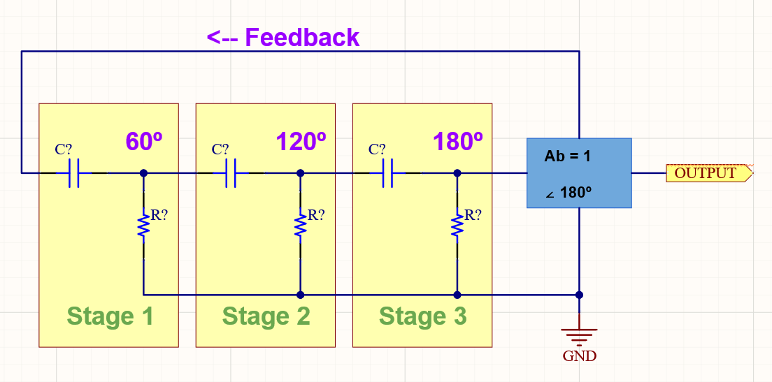
The RC network of an RC oscillator shifts the phase of the signal by 180 degrees.
The positive feedback is needed to shift the phase of the signal to another 180 degrees. This phase shift then gives us 180 + 180 = 360 of phase shift, which is effectively the same as 0 degrees. Therefore, the total phase shift of the circuit needs to be 0, 360, or another multiple of 360 degrees.
We can use the fact that a phase shift occurs between the input to an RC network, and the output from the same network, by using interconnected RC elements in the feedback branch. In the picture above, we can see that each cascaded RC network provides a 60 degree out phase voltage lag. Three networks together produce a 180-degree phase shift.
For ideal RC networks, the maximum phase shift can be 90 degrees. Therefore, to create a 180-degree phase shift, oscillators require at least two RC networks. However, it is challenging to achieve precisely 90 degrees of phase shift with each RC network stage. We need to use more RC network stages cascaded together to produce the required value and the desired oscillation frequency.
A pure or ideal single-pole RC network would produce a maximum phase shift of precisely 90 degrees. For oscillation, we require 180 degrees of phase shift, therefore, to create an RC oscillator, we must use at least two single-pole networks.
The RC network's actual phase depends on the chosen resistor and capacitor value for the desired frequency. The phase angle is determined using these formulas:

By cascading several RC networks, we can obtain 180 degrees of phase shift at the chosen frequency. This cascade of networks forms the base for the RC oscillator, otherwise known as Phase Shift Oscillator. Adding an amplifying stage utilizing a bipolar junction transistor or inverting amplifier, we can produce a 180-degree phase shift between its input and output to provide the full 360-degree shift back to 0 degrees that we require, as mentioned above.
Basic RC Oscillator Schematic
The primary RC Oscillator circuit produces a sine wave output signal using regenerative feedback obtained from the RC ladder network. Regenerative feedback occurs due to the ability of the capacitor to store an electric charge.

The Resistor Capacitor feedback network can be connected to produce leading phase shift (phase advance network) or can be connected to create a lagging phase shift (phase retard network.) One or more resistors or capacitors from the RC phase shift circuitry can be changed to modify the frequency of the network. This change can be made by keeping resistors the same and using variable capacitors because capacitive reactance varies with frequency. However, for the new frequency, there could be a requirement to adjust the amplifier's voltage gain.
If we choose the resistors and capacitors for RC networks, then the frequency of RC oscillations would be:

R - Feedback resistors resistance
C - Feedback capacitors capacitance
N - Number of RC networks cascaded
However, the combination of the RC Oscillator network works as an attenuator, and it reduces the signal by some amount as it passes through each RC stage. So voltage gain of the amplifier stage should be sufficient to restore lost signal.
The more common RC oscillator circuit is an Op-Amp Phase-Lead RC Oscillator.

The RC network needs to be connected to the inverting input of the Op-Amp, making it the inverting amplifier configuration. The inverting configuration gives 180 degrees of phase shift at the output, leading to a total of 360 degrees combined with the RC networks.
The other configuration of RC oscillator is the operational amplifier phase lag oscillator.


LC Oscillator
LC or Inductor-Capacitor Oscillator is a type of oscillator which utilizes a tank circuit to produce positive feedback for sustaining oscillation. The schematic contains an inductor, capacitor, and also an amplifying component.
Working Principle
The tank circuit is a capacitor and inductor connected in parallel, the diagram above also includes the switch and voltage source for ease of demonstration of the working principle when the switch is connecting the capacitor to the voltage supply, the capacitor charges.

When the switch connects the capacitor and inductor, the capacitor discharges through the inductor. The increasing current through the inductor starts to store energy by inducing an electromagnetic field around the coil.
When the switch connects the capacitor and inductor, the capacitor discharges through the inductor. The increasing current through the inductor starts to store energy by inducing an electromagnetic field around the coil. After discharging the capacitor, the energy from it has transferred into the inductor as an electromagnetic field. As the energy flow from the capacity decreases, current flow through the inductor decreases - this causes the inductor's electromagnetic field to fall as well. Due to electromagnetic induction, the inductor will create back EMF, which is equal to L(di/dt) in opposition to the change in current. This back EMF then begins to charge the capacitor. Once the capacitor has absorbed the energy from the inductor's magnetic field, the energy is stored once again as an electrostatic field within the capacitor.
If we had an ideal inductor and capacitor, this circuit could generate the oscillations forever. However, a capacitor has current leakage, and inductors have resistance. In real life, however, the oscillations would look as below, as energy is lost. This loss is called damping.

If we want to sustain the oscillations, we need to compensate for the loss of energy from the tank circuit through the addition of active components to the circuit, such as bipolar junction transistors, electric field-effect transistors, or operational amplifiers. The primary function of the active components is to add the necessary gain, help generate positive feedback, and to compensate for the loss of energy.
Tuned Collector Oscillator

The tuned collector oscillator is a transformer and a capacitor connected in parallel and switched with a transistor. This circuit is the most basic LC oscillator schematic. The primary coil of the transformer and capacitor forms the tank circuit, with the secondary coil providing positive feedback, which returns some of the energy produced by the tank circuit to the base of the transistor.
Colpitts Oscillator
A Colpitts Oscillator is an LC Tank oscillator which has been very common in RF applications. It’s suitable for applications up to several hundred megahertz. This circuit consists of two capacitors in series, forming a voltage divider, which provides feedback to the transistor, with an inductor in parallel. While this oscillator is relatively stable, it can be hard to tune and is often implemented with an emitter follower circuit so as not to load the resonant network.

Clapp Oscillator
To overcome the difficulties tuning the Colpitts oscillator to a specific frequency in production, a variable capacitor in series with the inductor is often added, forming a Clapp Oscillator. This modification allows the circuit to be tuned during production and servicing to the specific frequency required. Unfortunately, this type of LC oscillator is still quite sensitive to temperature fluctuations and parasitic capacitance.

Ceramic Resonator
Piezoelectric ceramic material with two or more metal electrodes (typically 3) forms the basis of a ceramic resonator. In an electronic circuit, the piezoelectric element resonates mechanically, which generates an oscillating signal of a specific frequency - like a tuning fork. Ceramic resonators are low cost; however, the frequency tolerance of ceramic resonators is only about 2500 - 5000 ppm. This tolerance of 0.25% to 0.5% of the target frequency is not suitable for precision applications, but they can be a considerable cost saving where absolute accuracy is not required.

With frequencies from below 1kHz to beyond 1GHz, there is a range of different materials and vibration modes that ceramic resonators use. It can be essential to understand the method of resonance used in a device you are placing into your design. Environmental factors such as vibration and shock could impact the function of the resonator within your circuit.

Quartz Oscillator
The Quartz oscillator is the most common type of crystal oscillator on the market. Where accuracy and stability are critical, the primary choice is crystal oscillators and their variants. A crystal oscillator stability is measured in ppm (parts per million), and stability could be somewhere around 0.01% to 0.0001% over -20 to +70 Celsius, depending on the specific device. An RC oscillator's stability can at best be 0.1% and LC 0.01%, they are more typically around 2% and are very sensitive to temperature changes. A quartz crystal can oscillate with very little power required to keep it activated compared to many other oscillators, making them perfect for low power applications.
When the crystal is shock excited by either a physical compression or, in our case, an applied voltage, it will vibrate mechanically at a specific frequency. This vibration will continue for some time, generating an ac voltage between its terminals. This behaviour is the piezoelectric effect, the same as a ceramic resonator. By comparison to an LC circuit, the crystal's oscillation after the initial excitation will last longer — a result of the crystal's naturally high Q value. For a high-quality quartz crystal, a Q of 100,000 is not uncommon. LC circuits typically have a Q of around a few hundred. However, even with the much higher Q, they cannot resonate forever. There are losses from the mechanical vibration, so it needs an amplifying circuit like RC and LC oscillators. For most devices that will take an external crystal clock source, this will be integrated into the device, and the only additional electronic components required are the load capacitors. The load capacitors are essential; if the capacitance of these is incorrect, the oscillator will not be stable. Typically, the datasheet for the oscillator will contain suggested values, or provide an equation to calculate the correct value for your circuit.
Other things to consider:
- Place both the capacitors and the quartz crystal as close to MCU as possible
- Use as short and wide traces as possible to prevent parasitic inductance.
There are many variants of the crystal oscillator; however, beyond a typical crystal, or "XO" you will typically only use the other options for specialised applications. These specialised oscillators can be very expensive and have astonishingly stable and precise oscillations in incredibly challenging environments where absolute precision is required. The vast majority of projects will not need anything beyond a TCXO from the list below, but you might find them interesting to research further.
This list is from Wikipedia:
- ATCXO — Analog temperature controlled crystal oscillator
- CDXO — Calibrated dual crystal oscillator
- DTCXO — Digital temperature compensated crystal oscillator
- EMXO — Evacuated miniature crystal oscillator
- GPSDO — Global positioning system disciplined oscillator
- MCXO — Microcomputer-compensated crystal oscillator
- OCVCXO — oven-controlled voltage-controlled crystal oscillator
- OCXO — Oven-controlled crystal oscillator
- RbXO — Rubidium crystal oscillators (RbXO), a crystal oscillator (can be an MCXO) synchronized with a built-in rubidium standard which is run only occasionally to save power
- TCVCXO — Temperature-compensated voltage-controlled crystal oscillator
- TCXO — Temperature-compensated crystal oscillator
- TMXO – Tactical miniature crystal oscillator
- TSXO — Temperature-sensing crystal oscillator, an adaptation of the TCXO
- VCTCXO — Voltage-controlled temperature-compensated crystal oscillator
- VCXO — Voltage-controlled crystal oscillator
Crystal Oscillator Modules
Suppose you're looking for a precise clock source for an application that does not have the amplification circuitry to make use of a crystal oscillator. In that case, an oscillator module might be a great solution. These modules have all the necessary circuitry built in to provide an amplified and buffered clock for whatever application you require. As with many fully integrated devices, you pay for convenience, the prices are typically much higher than the crystal oscillator itself, and they have a larger footprint. Despite this, they can still be smaller than building oscillator amplification and buffer circuitry and have no worries about stability.
Most oscillator modules have a crystal and CMOS inverter gate, using a Pierce oscillator circuit. Although CMOS inverters are less stable and have higher power consumption than transistor-based oscillators, CMOS inverter-based gates are easy and entirely usable in many applications.
MEMS Oscillators
MEMS or microelectromechanical system oscillators are precise timing devices based on MEMS technology, and are a relatively new technology. MEMS oscillators consist of MEMS resonators, OpAmps, and additional electronic components to set or adjust their output frequencies. MEMS oscillators often include phase-locked loops that produce selectable or programmable output frequencies.
The operation of MEMS resonators is similar to a tiny tuning fork that rings at high frequencies. Because MEMS devices are small, they can ring at very high frequencies, with their tuned resonant structures producing frequencies from tens of kHz to hundreds of MHz.
MEMS resonators are mechanically driven and fall into two categories: electrostatic and piezoelectric. Primarily, MEMS oscillators will use electrostatic transduction, as piezoelectric transduction resonators are not sufficiently stable. Piezoelectric transduction MEMS resonators find use in filtering applications.
One of the major advantages of MEMS Oscillators is that they can be used for multiple loads, replacing multiple crystal oscillators within a circuit. This feature can offer reductions in price and board real estate used by oscillator circuits significantly. Compared to other oscillator circuits, even crystal oscillators, the power consumption of MEMS devices is extremely low because of the smaller core current draw. The low power draw can allow devices running from a battery to run substantially longer, or negate the need to turn off the primary oscillator circuit to save power. MEMS oscillators, unlike other oscillators, do not require any external components to operate, offering further space and cost savings. Early MEMS oscillators struggled somewhat with stability, and options are on the market with +/- 8 parts per billion of frequency stability, if you are willing to pay for it.
Silicon Oscillators
As mentioned at the start of the article, many devices have oscillators integrated into their silicon. Silicon oscillators are mostly the same, just in a separate package. This integrated circuit gives you a complete RC oscillator circuit built from silicon. It provides better matching and compensation that you can typically make for a similar cost using passive components, in a smaller package. Silicon oscillators can be a great asset for devices that will undergo shock or experience vibrations, as they have no mechanically resonant elements. On most supplier's websites, you'll find these under the Integrated Circuits category rather than the Oscillators category.
In addition to the advantages over other oscillators in harsh environments, a silicon oscillator is typically programmable. Programming options depend on the specific device; however, a frequency setting resistor or SPI/I2C interface is common. While silicon oscillators usually have a relatively poor frequency error of about 1-2%, they are compact and require only an external power supply bypass capacitor. They can be a low-cost alternative to other types of oscillators in non-precision applications.
Summary
Choosing the optimal clock source is not easy. There are many factors, such as general stability, sensitivity over temperature, vibration, humidity, EMI, cost, size, power consumption, sophisticated layout, and additional components.
There are many applications where integrated RC or silicon oscillators are suitable as those applications do not require additional accuracy. Utilizing internal oscillator can save design time, cost, and reduce engineering risk. However, modern-day applications increasingly require high accuracy, which demands the use of an external oscillator, such as quartz crystal, ceramic, or MEMS.
As an example, high-speed USB requires a minimum 0.25% frequency accuracy, while some other external communications can work correctly with clock sources of 5%, 10%, or even 20% stability. Other high-speed busses and RF applications often require much greater frequency precision than USB.
The power consumption of oscillators for microcontrollers depends on the feedback amplifier supply current and capacitance values used. Power consumption of those amplifiers mostly depends on frequency, so if you want to design a very low power device, consider lowering your clock frequency to the minimum at which your device can still complete its work. Often you will find a microcontroller has a lot of leftover clock cycles, all of which are consuming unnecessary power.
Ceramic resonator circuits typically specify larger load capacitance values than crystal circuits and draw still more current than a crystal circuit using the same amplifier. By comparison, crystal oscillator modules usually draw between 10mA and 60mA of supply current because of the temperature compensation and control functions included.
There are many types of oscillators available on the market, each with their own pros and cons. For general purpose applications where precise timing is not absolutely critical, you can use almost any oscillator device or circuit that meets the frequency demands. For higher precision circuits you may want to consider higher cost devices such as MEMS oscillators that can offer parts per billion of frequency stability even over a large temperature range, however, expect to pay tens or hundreds of dollars per oscillator.
If you’re building an LED controller or similar sorts of circuits that only need a microcontroller to run some management or user interface code the integrated RC oscillator will provide you with everything you need. Suppose you’re working on a deep-sea submersible that can precisely track its position. In that case, an oscillator that has a stability of just a few parts per billion over a wide range of temperatures might be the minimum you can get away with. The more tightly you want to integrate sensor data, or the narrower band you want to use for radio communications, the more stable your oscillator must be. Suppose you are multiplying your frequency substantially, for example. In that case, you are creating a gigahertz signal from a megahertz oscillator, the more stable you will need the oscillator to be as any error is going to be magnified.
Wondering more about what is an oscillator? Call an expert at Altium.

About Author
Related Resources
Table of Contents
- Performance Comparison for Oscillators
- RC Oscillators
- Working Principle
- Basic RC Oscillator Schematic
- LC Oscillator
- Working Principle
- Tuned Collector Oscillator
- Colpitts Oscillator
- Clapp Oscillator
- Ceramic Resonator
- Quartz Oscillator
- Crystal Oscillator Modules
- MEMS Oscillators
- Silicon Oscillators
- Summary
Design to Release, Without the Friction
- Keep reviews tied to the right version
- Reduce handoff confusion and rework
- Spot sourcing and release risk earlier
- Work solo, share when needed
Get Started
Thank you, you are now subscribed to updates.

